10
11
ENGLISH
ENGLISH
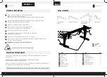
4 mm Allen Key (included)
6 mm Allen Key (included)
Electric Screwdriver
and/or Power Drill
Tape Measure
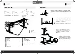
TOOLS / PARTS LIST
M6×35 Machine Screw
Frame
Handset
M6×30 Machine Screw
M10×30 Countersunk
head Machine Screw
Phillips Head Screwdriver
and/or Power Drill
Tape Measure
4mm Allen Wrench (included)
Side Bracket
Center Rail
Lifting Column
Foot
Adapter Buckle
Adapter
S
T
5×20 Wood Screw
S
T
5×16 Wood Screw
15
15
Power Cord
6mm Allen Wrench (included)
1
9
2
10
3
11
4
12
5
13
6
6
6
14
7
15
8
Side Bracket
2
Frame 4
Center Rail
2
Lifting Column
1
Foot 2
Handset 2
Control Box
1
Adapter Buckle
1
Adapter 1
ST5 × 20 Wood Screw
12
M6 × 35 Machine Screw
8
ST5 × 16 Wood Screw
2
M6 × 30 Machine Screw
8
M10 × 30 Countersunk head Machine Screw 4
Power Cord
1
Nr. Part
Qty
Nr. Part
Qty
7
ASSEMBLING
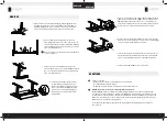
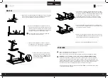
Align the holes of the side bracket
(1)
, the frame
(2)
, and the lifting column
(4)
.
Then put the M6 × 35 machine screw with the round head
(11)
into the holes and
tighten the screws with a 4 mm Allen Key. Repeat on the other side.
Insert the center rail
(3)
into the frame
(2)
on both sides, and ad-
just the appropriate position (note: the word „MAX“on the center
rail can‘t be completely exposed). Then put the M6 x 30 machine
screw with the round head
(13)
into the position as shown in the
figure and tighten with a 4 mm Allen Key.
If you drop a screw inside the frame end, simply tilt to retrieve.
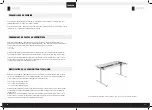
Align the holes on the foot
(5)
with the holes on the lifting
column
(4)
. Put the M10 × 30 countersunk head machine
screws
(14)
into the foot and tighten the screws with the
6 mm Allen Key.
Place the table frame on the bottom side of the
table surface and adjust the position of the table
frame to the middle of the desktop. Put the ST5 ×
20 wood screws
(10)
into the corresponding holes
on the side bracket
(1)
and fix them with a electric
screwdriver.
Align the holes of the side bracket (1), the frame (2), and the lifting column (4).
Then put the M6×35 machine screw
with round head (11) into the holes,
and tighten the screws with a 4MM hexagon wrench. Repeat on the other side.
Insert the center rail (3) into the frame (2) on both sides, and adjust the appropriate position (note: the word
"MAX" on the center rail can't be completely exposed). Then put the M6 x30 machine screw with round
head (13) into the position as shown in the figure, and tighten with a 4MM hexagon wrench.
If you drop a screw inside the frame end , simply tilt to retrieve.
Align the holes on the foot (5) with the holes on the lifting column (4). Put the
M10×30 countersunk head machine screws (14) into the foot, and tighten the
screws with a 6MM hexagon wrench.
Put the table frame on the desktop and adjust the position of the table frame to the middle of the desktop. Put the ST5×20
wood screw
s (10) into the corresponding holes on the side bracket (1) and fix them with a Phillips screwdriver.
4
4
1
11
2
2
2
3
13
5
14
4
10
1
2.
1.
3.
4.
Align the holes of the side bracket (1), the frame (2), and the lifting column (4).
Then put the M6×35 machine screw
with round head (11) into the holes,
and tighten the screws with a 4MM hexagon wrench. Repeat on the other side.
Insert the center rail (3) into the frame (2) on both sides, and adjust the appropriate position (note: the word
"MAX" on the center rail can't be completely exposed). Then put the M6 x30 machine screw with round
head (13) into the position as shown in the figure, and tighten with a 4MM hexagon wrench.
If you drop a screw inside the frame end , simply tilt to retrieve.
Align the holes on the foot (5) with the holes on the lifting column (4). Put the
M10×30 countersunk head machine screws (14) into the foot, and tighten the
screws with a 6MM hexagon wrench.
Put the table frame on the desktop and adjust the position of the table frame to the middle of the desktop. Put the ST5×20
wood screw
s (10) into the corresponding holes on the side bracket (1) and fix them with a Phillips screwdriver.
4
4
1
11
2
2
2
3
13
5
14
4
10
1


