18
19
Placez le combiné
(6)
sur le bord du bureau où vous le souhaitez. Fixez à
l‘aide de vis à bois ST5 × 16
(12)
le combiné sur le bureau. Branchez le fil
du combiné dans le boîtier de commande.
MONTAGE
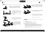
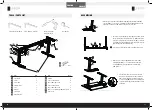
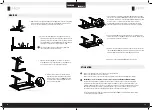
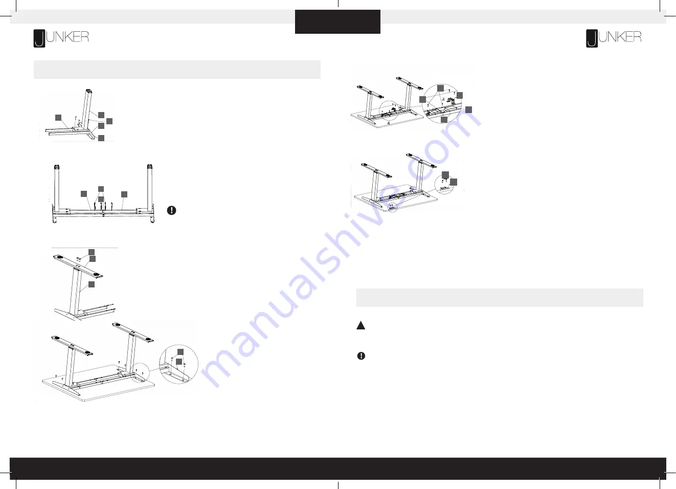
Alignez les trous du support latéral
(1)
, du cadre
(2)
et de la colonne de levage
(4)
.
Insérer ensuite la vis à métaux M6 × 35 à tête ronde
(11)
dans les trous et serrer
les vis avec une clé hexagonale de 4 mm. Répétez de l‘autre côté.
Insérez le rail central
(3)
dans le cadre
(2)
des deux côtés et
ajustez la position appropriée (remarque: le mot „MAX“ sur le rail
central ne peut pas être complètement exposé). Ensuite, placez la
vis à métaux M6 x 30 à tête ronde
(13)
dans la position indiquée
sur la figure et serrez avec une clé hexagonale de 4 mm.
Si vous laissez tomber une vis à l‘intérieur de l‘extrémité du
cadre, inclinez simplement pour récupérer
Alignez les trous du pied
(5)
avec les trous de la colonne de
levage
(4)
. Placez les vis à tête fraisée M10 × 30
(14)
dans le
pied et serrez les vis avec une clé hexagonale de 6 mm.
Placez le cadre de table sur le bureau et ajustez
la position du cadre de table au milieu du bureau.
Placez les vis à bois ST5 × 20
(10)
dans les trous
correspondants du support latéral
(1)
et fixez-les
avec un tournevis cruciforme.
Align the holes of the side bracket (1), the frame (2), and the lifting column (4).
Then put the M6×35 machine screw
with round head (11) into the holes,
and tighten the screws with a 4MM hexagon wrench. Repeat on the other side.
Insert the center rail (3) into the frame (2) on both sides, and adjust the appropriate position (note: the word
"MAX" on the center rail can't be completely exposed). Then put the M6 x30 machine screw with round
head (13) into the position as shown in the figure, and tighten with a 4MM hexagon wrench.
If you drop a screw inside the frame end , simply tilt to retrieve.
Align the holes on the foot (5) with the holes on the lifting column (4). Put the
M10×30 countersunk head machine screws (14) into the foot, and tighten the
screws with a 6MM hexagon wrench.
Put the table frame on the desktop and adjust the position of the table frame to the middle of the desktop. Put the ST5×20
wood screw
s (10) into the corresponding holes on the side bracket (1) and fix them with a Phillips screwdriver.
4
4
1
11
2
2
2
3
13
5
14
4
10
1
2.
1.
3.
4.
Placez le boîtier de commande et l‘adaptateur
(9)
au milieu du cadre
(2)
.
Fixez avec une vis taraudeuse
(10)
dans les trous des deux côtés du boîtier
de commande. Placez la boucle de l‘adaptateur
(8)
sur l‘adaptateur et fixez
les vis à bois ST5 × 20 dans les trous des deux côtés de la boucle
de l‘adaptateur. Branchez le fil moteur de la colonne dans le boîtier de
commande. Branchez le fil de l‘adaptateur dans le boîtier de commande.
Branchez le cordon d‘alimentation
(15)
dans une prise 230 V
6.
8.
Align the holes of the side bracket (1), the frame (2), and the lifting column (4).
Then put the M6×35 machine screw
with round head (11) into the holes,
and tighten the screws with a 4MM hexagon wrench. Repeat on the other side.
Insert the center rail (3) into the frame (2) on both sides, and adjust the appropriate position (note: the word
"MAX" on the center rail can't be completely exposed). Then put the M6 x30 machine screw with round
head (13) into the position as shown in the figure, and tighten with a 4MM hexagon wrench.
If you drop a screw inside the frame end , simply tilt to retrieve.
Align the holes on the foot (5) with the holes on the lifting column (4). Put the
M10×30 countersunk head machine screws (14) into the foot, and tighten the
screws with a 6MM hexagon wrench.
Put the table frame on the desktop and adjust the position of the table frame to the middle of the desktop. Put the ST5×20
wood screw
s (10) into the corresponding holes on the side bracket (1) and fix them with a Phillips screwdriver.
4
4
1
11
2
2
2
3
13
5
14
4
10
1
Putthecontrolboxandadapter(9)intothemiddleofthe
frame (2).Fix with tapping screw (10) into the holes on
bothsidesofthecontrolbox.Puttheadapterbuckle(8)
on the adapter, and fix the
ST5×20 wood screw
s
into
the holes on both sides of the adapter buckle. Plug the
motor wire of the column into the control box.Plug the
wireoftheadapterintothecontrolbox.
Double-check that the wood screws are not too long for your desktop
and won’t puncture the surface when screwed all the way in.
We recommend that you pre-drill any holes needed for fasteners
if your desktop is not pre-drilled. Never use countersunk screws.
10
8
9
2
7
Put the handset (6) on the edge of the desktop where you
like. Fix with
S
T
5×16 wood screw
s (12) the handset on
the desktop. Plug the wire of the handset into the control
box.
6
12
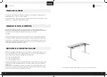
Turn the assembled desk right-side up. With at least two people, grab the DESK BASE (not the desktop) and turn the
desk right-side up. Adjust the pre-installed glides on the Feet (part 5) as needed.
Plug the Power Cord (part 15) into a 230V outlet.
5.
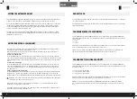
Retournez le bureau assemblé à droite. Avec au moins deux personnes, sai-
sissez la BASE DU BUREAU (pas le bureau) et tournez le bureau vers le haut.
Ajustez les patins pré-installés sur les pieds
(5)
selon les besoins
7.
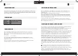
Assurez-vous qu‘aucun obstacle ne se trouve sur le chemin du bureau.
Assurez-vous que le bureau ne touche aucun mur.
Assurez-vous que tous les cordons sont de longueur appropriée pour s‘adapter au changement de hauteur.
IMPORTANT: vous devez réinitialiser le bureau avant de l‘utiliser. PROCÉDURE DE RÉINITIALISATION:
Appuyez sur le bouton BAS du combiné (partie 6) et maintenez-le enfoncé jusqu‘à ce que le bureau atteigne
sa hauteur la plus basse. Relâchez le bouton BAS. Appuyez et maintenez enfoncé le bouton BAS jusqu‘à ce que
l‘affichage LED indique «RST» ou environ 10 secondes sur les modèles de combinés non LED. Relâchez le bouton
BAS. Appuyez et maintenez à nouveau le bouton BAS jusqu‘à ce que le bureau s‘abaisse un peu plus, monte
légèrement et s‘arrête. Relâchez le bouton BAS. Votre bureau est maintenant prêt à l‘emploi.
La base du bureau peut être réglée en appuyant sur le bouton UP ou DOWN et en le maintenant enfoncé jusqu‘à
ce que la hauteur souhaitée soit atteinte
UTILISATION
!
FRANÇAIS
FRANÇAIS


