


8.
Use a ratcheting torque screwdriver to apply a torque of 1.53 nm to each of the terminal
block screws. See
.
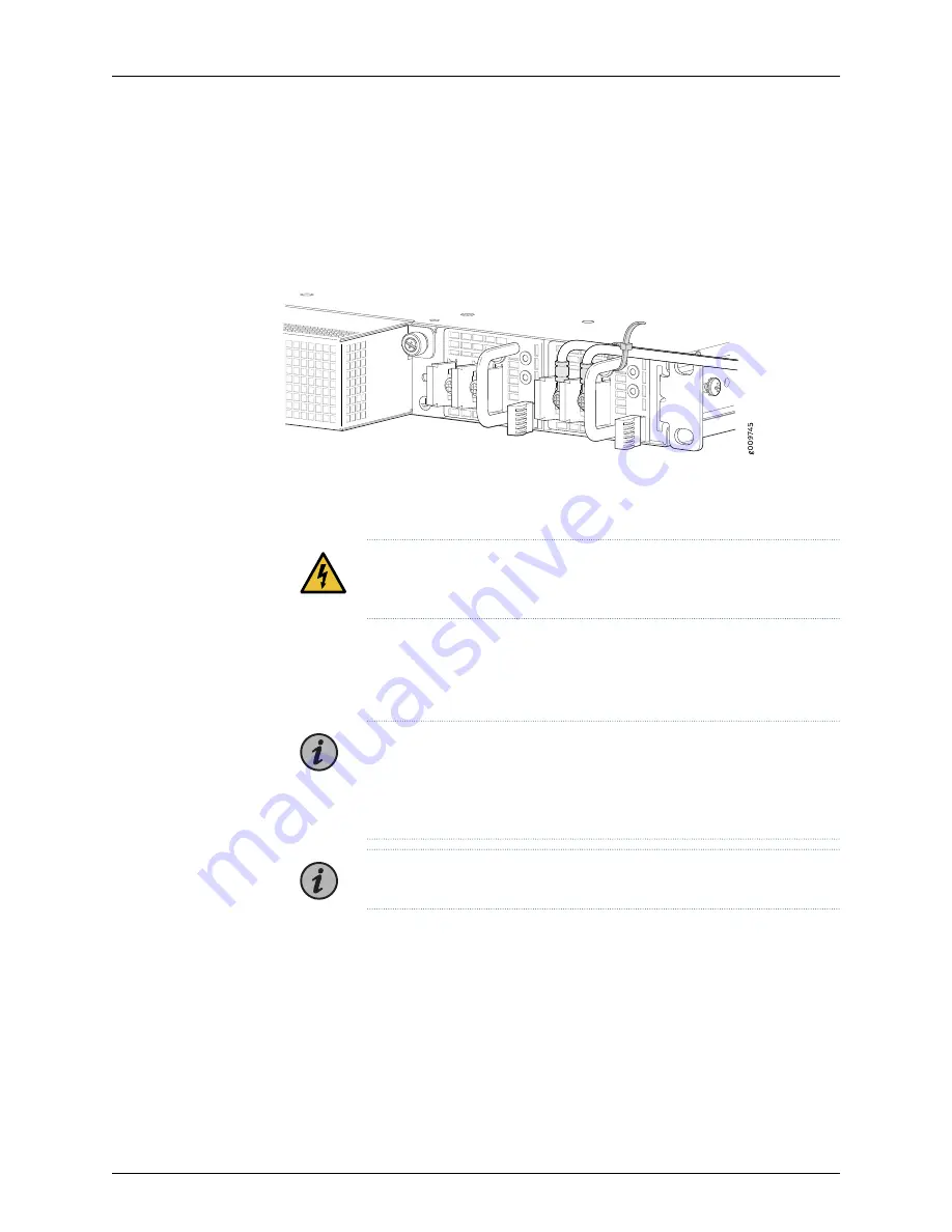
9.
Use a tie-wrap to secures the cables. See
Figure 8: Connecting the DC Power
10.
Repeat Step
through Step
for each power supply you are connecting to power.
WARNING:
Ensure that the power cables do not block access to device
components or drape where people can trip on them.
11.
Replace the plastic cover.
12.
Close the input circuit breaker.
NOTE:
We recommend that the 48-VDC facility DC source be equipped
with a circuit protector rated as required by local code. For the voltage
range, see the TCX1000 Programmable ROADM Hardware Guide at
https://www.juniper.net/documentation/
NOTE:
The TCX1000-RDM20 powers on as soon you connect the power.
13.
Verify that the LEDs on each power supply are lit green.
If the LEDs are lit yellow, remove power from the power supply, and replace the power
supply (see
Removing a Power Supply from a TCX1000-RDM20
in the
TCX1000
Programmable ROADM Hardware Guide
). Do not remove the power supply until you
have a replacement power supply ready; the power supplies must be installed in the
TCX1000-RDM20 to ensure proper airflow.
11
Copyright © 2018, Juniper Networks, Inc.
Connecting DC Power to the TCX1000-RDM20