2
Hardware Installation
57
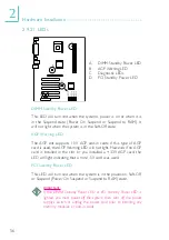
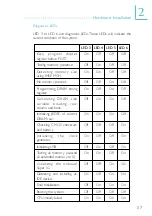
Diagnostic LEDs
LED 3 to LED 6 are diagnostic LEDs. These LEDs will indicate the
current condition of the system.
Ear ly progr am chipset
register before POST.
Testing memory presence.
Detecting memor y size
using 845E MCH.
No memory present.
Programming DRAM timing
register.
Calculating DRAM size
var iable including row,
column and bank.
Initializing JEDEC of current
DRAM row.
Checking CMOS checksum
and battery.
Initializing
the
clock
generator.
Initializing USB.
Testing all memor y (cleared
all extended memory to 0).
Initializing the onboard
Super IO.
Detecting and installing an
IDE device.
Final initialization.
Booting the system.
CPU initially failed.
LED 3
On
Off
On
Off
On
Off
On
Off
On
Off
On
Off
On
Off
Off
On
LED 4
Off
On
On
Off
Off
On
On
Off
Off
On
On
Off
Off
On
Off
On
LED 5
Off
Off
Off
On
On
On
On
Off
Off
Off
Off
On
On
On
Off
On
LED 6
Off
Off
Off
Off
Off
Off
Off
On
On
On
On
On
On
On
Off
On


