background image

– 125 –

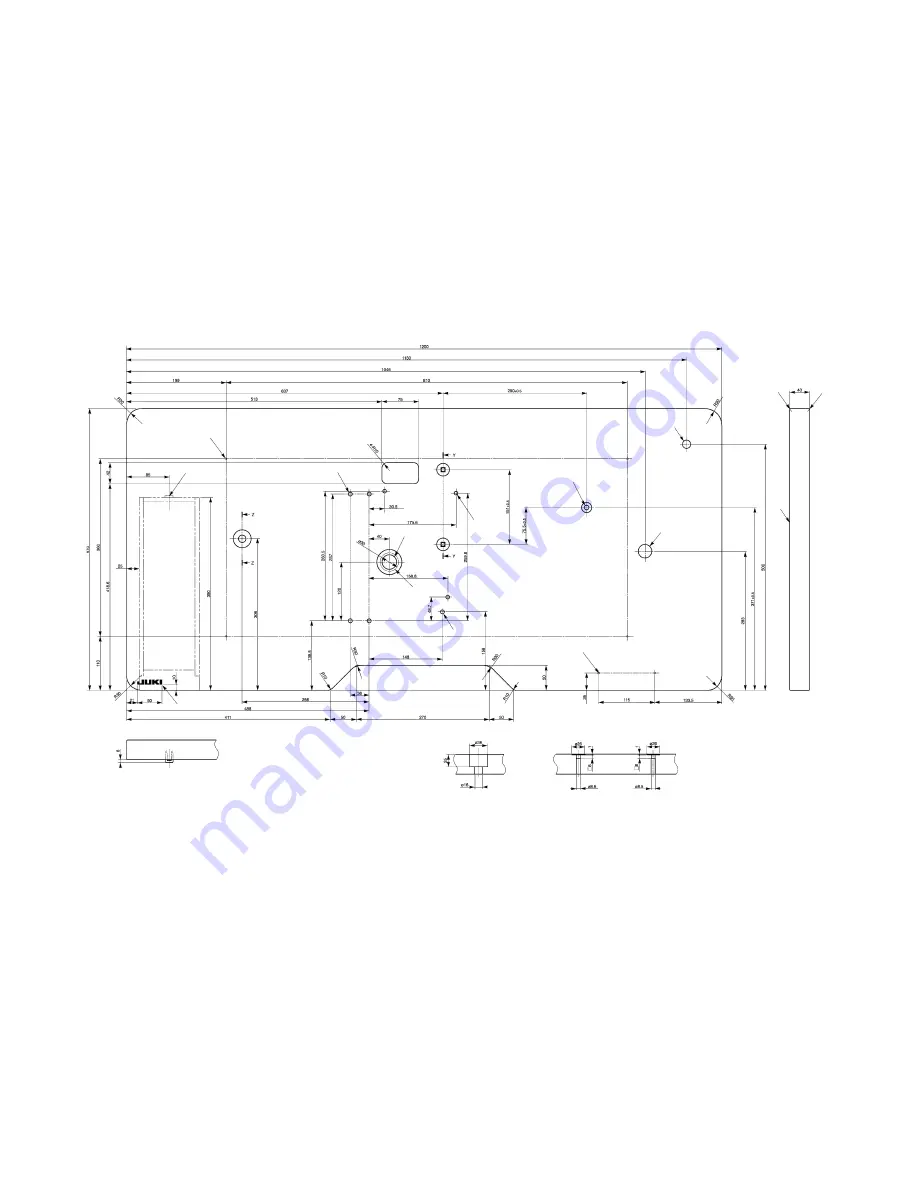
 13.  Table drawings
 (1)  Table type for longitudinal Installation

Z-Z

Y-Y

1

2

5

4

6

7

9

!0

!1

!2

!3

!4

!3

3

8

1

 4- drilled hole 2, 10 deep on the rear side (Stand installing hole) 

8

 Drilled hole 8

2

 Drawer stopper installing position One place on the rear side 

9

 Drilled hole 9, 20 spot face 17 deep

3

 JUKI logotype 

!0

 2- drilled hole 2, 10 deep on the rear side (Power switch installing hole)

4

 4- drilled hole 8 

!1

 Drilled hole 17

5

 Drilled hole 30, 51 spot face 16 deep 

!2

 Drilled hole 28

6

 Oil drain funnel installing hole 

!3

 R2 (all corners)

7

 3- drilled hole 7, 6 deep 

!4

 Right side

For LK-1900AN
For LK-1901AN
For LK-1903AN
Part No.: 40006886

Содержание LK-1900AN

Страница 1: ...40111443 No E402 00 ENGINEER S MANUAL LK 1900AN Series Computer controlled High speed Bartacking Machine ...

Страница 2: ...nd other important information which are not covered in the Instruction Manual When carrying out the maintenance work on the sewing machine be sure to refer also to the Instruction Manual and the Parts List In addition for the motor for the sewing machine with thread trimmer refer to the separate Instruction Manual or This manual gives the Standard Adjustment on the former page under which the mos...

Страница 3: ...needle changing bobbin changing or oiling and cleaning 3 2 1 Electrical shock danger label DANGER This indication is given where there is an immediate danger of death or serous injury if the person in charge or any third party mishandles the machine or does not avoid the dangerous situation when operating or maintaining the machine WARNING This indication is given where there is a potentiality for...

Страница 4: ...alter the machine in order to prevent accident that can result in personal injury or death JUKI assumes no responsibility for damages or personal injury or death resulting from the machine which has been modified or altered Education and training 1 In order to prevent accident resulting from unfamiliarity with the machine the machine has to be used only by the operator who has been trained educate...

Страница 5: ...ified rated motor JUKI genuine product in order to prevent accident caused by burnout 2 If a commercially available clutch motor is used with the machine be sure to select one with an entan glement preventive pulley cover in order to protect against being entangled by the V belt Before operation 1 Be sure to make sure that the connectors and cables are free from damage dropout and looseness be for...

Страница 6: ...e blown fuse with a new one in order to prevent accident that can result in personal injury or death 9 Be sure to periodically clean up the air vent of the fan and inspect the area around the wiring in order to prevent fire accident of the motor Operating environment 1 Be sure to use the machine under the environment which is not affected by strong noise source electro magnetic waves such as a hig...

Страница 7: ...ne parts when replacing any of the machine parts JUKI assumes no responsibility for any accident caused by any part other than JUKI genuine one In addition in the event you cannot replace parts within the specified range immediately stop the re placement work and ask JUKI or distributor in your area for replacement of the parts 8 If the fuse has blown be sure to turn the power off and eliminate th...

Страница 8: ... parts be sure to turn the power off and wait for five minutes or more before opening the cover in order to prevent accident caused by unfa miliarity with the machine or electrical shock accident In addition do not carry out disassembly assem bly work with wet hands in order to prevent electrical shock accident 4 Be sure to carry out replacement work after having installed the machine in a stable ...

Страница 9: ...accidents due to dam aged electrical component s 15 In the event of a power failure be sure to turn OFF the power to the machine to protect against damaged electrical components 16 This sewing machine should be used under industrial environment Under general house hold environment the machine may cause poor reception when used in proximity of the television set or radio 17 When the sewing machine ...

Страница 10: ...is is a cover for preventing contact between the human body and the thread take up lever Electrical shock danger label EU type Refer to Elec trical shock danger label on page i In order to protect against electrical shock safety precau tions to be taken to avoid danger are written on this label CAUTION Motor cover This is a cover for preventing contact be tween the human body and the motor Warning...

Страница 11: ...fe position 24 17 Adjustment of the height of the moving knife and counter knife 24 18 Inclination of the blade point of the counter knife 26 19 Floating amount of the thread tension disk 26 20 Second thread tension connection disconnection 28 21 AT unit connection disconnection 30 22 Position of the mechanical origin 32 23 Adjustment of the Y origin sensor 32 24 Adjustment of the X origin sensor ...

Страница 12: ...rts 78 3 Table of the work clamp foot 80 9 Maintenance 82 1 Replacing the fuse 82 2 100V 200V voltage specification changeover 82 3 Greasing parts 83 4 Parts to which grease is applied 84 5 Grease up procedures for the specified position 91 10 Error list 92 11 Troubles and corrective measures 95 1 Mechanical parts 95 2 Sewing conditions 97 3 Electrical components 106 12 Circuit diagrams 117 1 Bloc...

Страница 13: ...andard semi rotary hook 16 Lubrication Hook minute quantity lubrication 17 Lubricating oil JUKI NEW Defrix oil No 2 equivalent to ISO VG32 Lubrication system 18 Grease 1 Penetration No 2 lithium grease 2 Templex N2 3 JUKI Grease A 4 JUKI Grease B Caution 2 19 Memory medium EEP ROM 128 Kbyte EP ROM 32 Kbyte 20 Number of stitches that can be stored in memory Max 20 000 stitches 21 Enlarging Reducing...

Страница 14: ... 2 Configuration 1 Names of main unit 1 Sewing machine head 2 Work clamp foot 3 Thread stand 4 Operation panel 5 Power switch 6 Control box 7 Pedal switch 8 Power switch EU Type 1 2 3 4 5 6 7 8 ...

Страница 15: ...te where the sewing machine actually operates 2 Sewing LED This LED goes off at the time of setting state and lights up at the time of sewing state Change over can be performed with Ready key 3 Reset key This key is used for canceling error or returning the set value to the initial value 4 Mode key This key makes the setting mode of the memory switch 5 Feed forward key and Feed back ward key This ...

Страница 16: ...emove the main shaft motor 8 Refer to 3 Removal of the main shaft motor and coupling 4 Loosen the two set screws 0 Pay attention to possible injury at that time because the balancer 1 begins to turn when the set screw 0 is loosened 5 Loosen the two set screws 2 At that time the first set screw of the set screw 2 should be removed completely from the flat part of the main shaft 7 6 Loosen the two s...

Страница 17: ... the two each set screws 4 and 6 respectively Make sure that the first screw touches flatly on the main shaft 7 5 Push the hand pulley 0 in the direction of the arrow F so that the hand pulley gear A 6 is meshed with that the hand pulley gear B 9 In this state fix the pulley with the two set screws 4 6 Mount the main shaft motor 8 and the coupling 9 Refer to 3 Removal of the main shaft motor and c...

Страница 18: ...stment of the main shaft wheel position Standard adjustment The distance is 3 mm between the measuring plane A of the main shaft wheel 1 and the plane B of the middle bearing bush of the main shaft 3mm 1 2 A B ...

Страница 19: ... Adjustment procedures Results of Improper adjustment 1 Adjust the position of the main shaft wheel 1 and fix it with two set screws 2 ...

Страница 20: ...e four motor set screws 4 2 To remove the coupling 2 from the main shaft motor 3 loosen the two set screws 6 on the main shaft side Caution Turn the main shaft 1 in the direction of forward rotation A The screw hole that can be seen first is the No 1 screw Loosen the screws starting with the No 2 screw Tight ening should be done starting with the No 1 screw No 1 screw No 2 screw No 1 screw Flat se...

Страница 21: ...ositioned in the sidewise direction 2 Incorporation of the coupling in the main shaft motor 1 Provide a clearance of 0 5 mm between the coupling 2 and the main shaft motor 3 2 Apply the No 1 screw 5 of the coupling 2 to the shaft flat section of the main shaft motor 3 and fix it 3 Meshing of the coupling 1 Apply the set screw 6 No 1 screw of the main shaft motor side to the section between the two...

Страница 22: ...rews 5 At that time the second screws should be loosened first for the set screws 4 5 and 5 The first screws of the set screws 4 5 and 5 should be arranged so that they can come completely off the flat section of the oscillator shaft 6 3 Pull out the oscillator shaft 6 in the direction of the arrow A 4 Remove the main shaft 7 according to 1 Main shaft connection disconnection Then take out the cra...

Страница 23: ...rews 9 and then fix them so that the crank rod unit 2 is not displaced from the center of swinging Tighten the first screw first so that it comes in contact flatly with the main shaft 7 Then tighten the second one 6 Mount the lengthwise feed motor 2 and the crosswise feed motor mounting plate 3 using the two set screws 1 and four set screws 3 Refer to 27 Adjustment of the position of the X feed mo...

Страница 24: ...ondition Axial direction Keep the close contact with the main shaft eccentric cam 8 and the crank balancer 6 6 Lower shaft backlash adjustment and connection disconnection Standard adjustment 1 Size of lower shaft backlash is 0 1 mm at the tip of the driver 5 The shaft is required to rotate smoothly 2 Define the stop position of the lower shaft 6 so that the set screw 7 settles almost in the cente...

Страница 25: ...mproper adjustment 1 Lower shaft backlash 1 Loosen the two set screws 1 2 Turn the lower shaft rear metal 2 in the direction of the ar row and adjust the backlash keeping the metal to contact closely with Face A Size of backlash is 0 1 mm at the tip of the driver 5 The shaft is required to rotate smoothly 3 Tighten the two set screws 1 Caution When eliminate the backlash the direction of rota tion...

Страница 26: ... adjustment 1 When the oscillator is lightly swung by a finger in the direction of the arrow the oscillator 2 is fixed in the center position of swinging 8 Adjustment of hook oil amount Standard adjustment No 2 screw No 1 screw B 8 5 to 9 0 mm ...

Страница 27: ...nt for the lower shaft gear 3 accord ing to 6 Lower shaft backlash adjustment and connection disconnection Caution 1 In the case of disassembly and adjustment grease up treatment is always needed for the specified places 2 positions and the gear area A of the oscillator 2 2 When the crank rod under cam is removed actions for oscillator gear positioning must be taken without fail Refer to 4 Crank c...

Страница 28: ...Take them out of the oil tank 5 5 Release the cord clamp from the rear side of the bed of the oil drain pipe 7 6 Loosen the set screw 8 and take out the driver 9 7 Loosen the set screw 0 8 Remove the set screw 1 and pull out the shuttle race adjust shaft 2 9 Pull the shuttle 3 in the direction of the arrow C and take it out 10 Adjustment the height of the needle bar Standard adjustment A Engraved ...

Страница 29: ...on pipe 6 to touch the needle thread clamp connec tor link 5 Bundle the needle thread clamp sensor cord 6 the lubrication pipe 6 and the oil drain pipe 7 with the harness band 3 6 Pass the two lubrication pipes 6 through the cord clamp 9 and fix them with the set screw 1 7 Insert the two lubrication pipes 6 part B in the oil tank 5 Fix the oil tank 5 to the frame with the set screw 4 8 Fix the oil...

Страница 30: ... 18 11 Hook adjustment Standard adjustment For DP 17 For DP 5 0 05 to 0 1 mm ...

Страница 31: ... needle 8 as the front end face of driver 9 receives the needle 8 to prevent the needle from being bent Then tighten setscrew 4 of the driver 9 4 Loosen setscrew 3 of the shuttle and adjust the longitudinal position of the shuttle To do this adjustment turn shuttle race adjusting shaft 0 clockwise or counterclockwise to provide a 0 05 to 0 1 mm clearance between needle 8 and the blade point of inn...

Страница 32: ...cases the bearing 7 and the motor shaft seem to be tightly coupled Pull out the motor shaft in the direction of the arrow straightforward in order not to hurt the bearing 7 At that time the cam 1 may come down Handle it with care not to damage it 13 Thread trimmer and presser foot origin sensor adjustment Standard adjustment In the state of origin retrieval Start Switch ON in the test mode CP 6 th...

Страница 33: ...djustment and make sensor adjust ments Adjustment procedures Results of Improper adjustment 1 Start the test mode CP 6 2 Tread on the pedal for the retrieval of the thread trimmer and presser bar lifter cam origin 3 Using a bar 2 5 mm hexagonal wrench key corresponding 4 or the like confirm that the standard holes A and B of the sewing machine frame coincide with the standard hole C of the thread ...

Страница 34: ...Adjustment of the thread trimmer sensor Standard adjustment After the completion of origin retrieval in the test mode CP 6 Start Switch ON try to press the key 4 6 to 8 times At that time the thread trimmer sensor is turned ON The display 1 at the operation panel 10 00 Max 17 mm ...

Страница 35: ...r adjustment 3 Press the key 4 Confirm that the display 1 of the operation panel is changed over from 10 to 00 when the key is pressed within the range of 6 to 8 times 4 If the display changeover occurs deviating from the range of 6 times to 8 times or if the display changeover does not occur at all loosen the set screw 2 and make fine adjustments of the sensor slit 3 in the directions of the arro...

Страница 36: ...ndby state the distance from the needle plate 4 to the tip of the thread trimmer lever small 7 is 18 5 mm 17 Adjustment of the height of the moving knife and counter knife Standard adjustment Moving knife 8 The amount of mesh of the needle hole guide 6 with the moving knife 8 is 0 15 mm Counter knife 5 The height between the needle hole guide 6 and the blade of the counter knife 5 is 0 1 to 0 15 m...

Страница 37: ...roper adjustment 1 Adjustment of the height of the moving knife Adjustments should be based on the plate thickness of the washer 3 in the above illustration If the height seems to be inadequate select and use the parts as specified below Part No Name of part Thickness B242328000A Moving knife washer 0 4 mm B242328000B Moving knife washer 0 5 mm B242328000C Moving knife washer 0 6 mm B242328000D Mo...

Страница 38: ...bobbin thread uniformly the blade face of the counter knife 1 is made to have an inclination of 0 2 mm 19 Floating amount of the thread tension disk Standard adjustment When the sewing machine power supply is turned off AT solenoid 1 is OFF the gap between AT thread tension discs is 0 6 to 1 mm Close contact 0 6 to 1 mm ...

Страница 39: ...tension releasing pin adjust collar 5 not to let it rotate and loosen the nut 6 4 Turn the tension releasing pin adjust collar 5 and adjust the gap between the thread tension discs 7 Adjustment of thread tension disc floating 5 Hold the tension releasing pin adjust collar 5 and tighten the nut 6 Mount the thread tension cap 4 by means of the set screw 3 6 Turn on the power supply and set up the th...

Страница 40: ...Remove the two set screw 4 3 Move the AT link unit front 3 downwards in the direction of the Arrow A and pull out the pin block 5 from the hole of the thread tension releasing pin 6 of the second thread tension 1 4 Pull out the second thread tension 1 to remove it Arrow B 5 For reassembly follow the steps of 4 to 1 above ...

Страница 41: ...a cause of breaking the second thread ten sion 1 2 When tightening the set screw 4 this fixing action should be taken after the AT link unit front 3 has been moved to the left side in the direction of the arrow C If it is not moved to the left side in the direction of the arrow C the amount of tension disc floating may fail to be adjusted normally 3 After reassembly follow the steps for the adjust...

Страница 42: ...of the AT link unit rear 4 Be careful not to drop the washer 7 at that time Work becomes easier if the main shaft motor is removed 3 Lift the joint block 8 of the AT unit upwards and take it off the pin block 5 of the AT link unit rear 4 4 Draw out the AT link unit front 1 from the plane side in the direction of the arrow E and remove it 5 Remove the two set screws 9 and take out the AT solenoid u...

Страница 43: ...ion the parallelism of the two front and rear joint block 8 must also be secured without fail If the correct distance and parallelism are lost this can be a cause of AT mal function and normal sewing tension cannot be obtained 3 Upon the completion of all reassembly work confirm that there is a close contact between the thrust collar 3 and the AT solenoid unit 0 If any clearance is perceived loose...

Страница 44: ...igin Standard adjustment 23 Adjustment of the Y origin sensor Standard adjustment Work feed plate A 147mm LK 1900AN 1902AN 146mm LK 1901AN 1903AN B 61mm LK 1900AN 1902AN 62mm LK 1901AN 1903AN C 74mm LK 1900AN 1902AN 73mm LK 1901AN 1903AN ...

Страница 45: ...o 23 Adjust ment of the Y origin sensor and 24 Adjustment of the X origin sensor o The maximum area cannot be secured Adjustment procedures Results of Improper adjustment 1 Select the test mode No 2 CP 2 origin retrieval 2 Origin retrieval is conducted each time the pedal is trodden on Loosen the sensor slit set screw 1 and shift the position of the sensor slit plate 2 Apply the work feed plate to...

Страница 46: ... 34 24 Adjustment of the X origin sensor Standard adjustment 25 Adjustment of the wiper position Standard adjustment 1 5 mm or more ...

Страница 47: ...etween the wiper 2 and the needle so that this clearance attains 1 5 mm or more 2 Loosen screw 1 and adjust the distance A between the wiper 2 end plane and the needle center until this distance attains the values specified below After adjustments tighten the screw 1 firmly Distance A between the needle center and the wiper 2 end plane A mm Other than LK 1903AN 23 to 25 mm LK 1903AN only 15 to 17 ...

Страница 48: ...ustment of the position of the X feed motor and the Y feed motor Adjustment of the backlash of the driving gear Standard adjustment 1 Fix the Y feed motor 1 by pressing it in the direction of the arrow C 2 Fix the X feed motor 6 by pressing it in the direction of the arrow B ...

Страница 49: ...nt needle thread castoff may occur 3 If the wiper spring 1 position is inadequate the needle thread cannot be held correctly and this can be a cause of needle breakage Adjustment procedures Results of Improper adjustment 1 Loosen the two setscrews 2 and four setscrews 4 of the Y feed motor 1 and the two setscrews 4 of the X feed motor mounting plate 5 2 Pressing it in the direction of the arrow C ...

Страница 50: ...ear cover Standard adjustment The clearance between the feeder bar rear cover 1 and the upper surface of the work feed presser bar 4 is about 1mm When the feeder bar 5 is moved in the direction of the arrow A there must be a clearance at the notch part of the sewing machine frame 3 Machine bed Clearance ...

Страница 51: ...er bar 4 Then tighten the two set screws 2 3 Move the feeder bar 5 in the direction of the arrow A and confirm that there is a clearance at the notch part of the sewing machine frame 3 If there is no clearance and there is interfer ence with the sewing machine frame 3 the steps of 1 to 2 above should be repeated again Caution When tightening the set screws 2 the feeder bar rear cover 1 may be move...

Страница 52: ...he sewing machine frame 3 31 Adjustment of the bobbin winder amount Standard adjustment The position of the bobbin winder lever 1 is based on the standard that it is 14 mm apart from the bobbin winder shaft 2 Try to perform bobbin winding actually and make fine adjustments in the directions of the arrows A and B so that the amount of thread winding becomes adequate recommended value 80 to 90 of th...

Страница 53: ...bobbin winder lever 2 Start the sewing machine and wind the thread at the bobbin winder Confirm the amount of winding 1 If the amount of winding seems to be too much adjust the bobbin winder lever 1 in the direction of the arrow A 2 If the amount of winding seems to be too less adjust the bobbin winder lever 1 in the direction of the arrow B 3 If the winding state of the thread 7 around the bobbin...

Страница 54: ...r part A Caution If Part B is damaged this is the cause of thread breakage hangnail of thread stain on thread etc Therefore this part should be polished by the use of a buff or the like In particular the rear side should be handled with care 33 Shuttle felt Standard adjustment Two pieces of the shuttle felt 1 are inserted in the holes of the shuttle race 2 Confirm that the shuttle felts 1 are not ...

Страница 55: ...to hook the needle thread o Too much motion to the rear side will cause the moving knife to fail to hook the needle thread o Too much motion to the left side will cause the moving knife to fail to hook the bobbin thread Adjustment procedures Results of Improper adjustment 1 If the shuttle felt 1 seems to be protruded or it has been re placed with a new one push it in by means of tweezers or the li...

Страница 56: ...f wear seems to be too much around the pointed tip of the inner hook release the inner hook presser 1 and confirm that the dimensions of the hatched area on the rear side are 0 3 x 8 mm 35 Adjustment of the thread take up spring Standard adjustment Dimension A 1 ...

Страница 57: ...ockwise will increase the moving amount and the thread drawing amount will increase 2 Adjusting the pressure To change the pressure of the thread take up spring 1 insert a thin screwdriver into the slot of thread tension post 4 while screw 2 is tightened and turn it Turning it clockwise will in crease the pressure of the thread take up spring 1 Turning it counterclockwise will decrease the pressur...

Страница 58: ...e screw 1 If the hinge screw 1 cannot be seen from the open part of the needle thread clamp device 3 try to move the needle thread clamp connector link 6 by hand in the direction of A or B 2 Remove the four setscrews 2 of the needle thread clamp base and take out the needle thread clamp device 3 Open part ...

Страница 59: ...the needle thread clamp support plate complete 4 and the needle 5 is 3 3 to 3 7 mm and 1 7 to 2 3 mm respectively 3 If the distance seems to be inadequate loosen the four set screws 2 and move the needle thread clamp device 3 for adjustment Caution For the prevention of injury the distance should be checked only if the sewing LED is unlit Press the key twice after the power supply has been turned ...

Страница 60: ...hdrawn by 3 to 4 pulses from the needle thread clamp position refer to Caution the clearance A toward the needle thread clamp 3 becomes zero 0 Caution The needle thread clamp position is known to be the one that is one step returned from the most advanced position when the key is pressed in the test mode CP 7 1 7 to 2 3 mm 3 to 4 mm ...

Страница 61: ... the above mentioned steps 2 to 4 8 Using 3 to 4 pulses repeat the steps 2 to 6 above until the clearance A becomes 0 9 Tread on the pedal for needle thread clamp 3 origin retrieval and define the most advanced position by pressing the key once 10 Confirm that the distances between the needle thread clamp support plate complete 4 and the needle 5 are kept at 3 to 4 mm and 1 7 to 2 3 mm respectivel...

Страница 62: ...le thread clamp 4 begins to open the distance between the needle thread clamp 4 and the needle thread clamp base 5 becomes 21 mm 2 Needle thread clamp notch F position 1 When the needle thread clamp link complete 2 is pushed in Direction C and Part B of the needle thread clamp support plate complete 3 and the needle thread clamp 4 begins to open the distance between the needle thread clamp 4 and t...

Страница 63: ... mm release tim ing turns so slowly that needle thread remains on the back side of the material is caused 2 Needle thread clamp notch F adjustment 1 Loosen the two setscrews 7 2 Push the needle thread clamp link complete 2 in Direction C so that the distance between the needle thread clamp 4 and the needle thread clamp base 5 becomes 23 mm Move the needle thread clamp notch F 8 in Direction E ligh...

Страница 64: ...B MAZ157080BA E MAZ156080B0 C MAZ156080B0 C B25573720A0 Needle hole guide mm φB φC A Height of boss A 1 6 1 8 1 6 1 8 1 1 1 6 1 4 Outside diameter of boss B φ2 8 φ3 5 φ3 5 φ3 5 Diameter of hole C φ1 6 φ1 6 φ2 0 φ2 0 Part No MAZ15801000 MAZ15501000 14149603 MAZ15601000 MAZ15701000 14149900 D2426284Y00 Feed plate MAZ15502000 8 5 MAZ15602000 10 MAZ15702000 12 5 Items in are optional For common use Mo...

Страница 65: ...tandard length Y mm 1 34 6 6 3 4 3 4 18 44 6 3 4 0 2 35 8 8 19 45 8 3 10 10 20 10 4 12 12 21 12 5 36 6 6 22 16 6 37 8 8 23 46 6 0 3 4 7 10 10 24 10 8 12 12 25 12 9 38 6 6 26 47 6 6 3 4 3 4 10 39 8 8 27 10 10 11 10 10 28 48 6 6 12 40 6 6 29 10 10 13 41 8 8 30 49 5 5 5 3 0 2 5 14 10 10 31 8 8 8 15 42 6 6 32 50 5 5 5 16 43 8 8 33 8 8 8 17 10 10 Standard sewing lengths X and Y given above are given as...

Страница 66: ...at the test mode has become effective 2 The memory switch number can be modified with the and keys 3 Select a required number of memory switch by pressing the and keys then fix the number by pressing key to turn on the LED 4 Change the contents of the memory switch with the and keys 5 The factory shipment values can be recovered with the key 6 The contents of modification can be registered by pres...

Страница 67: ...ad trimming 0 to 200 0 U Changeover timing of thread tension at the time of thread trimming 6 to 4 1 32 0 28 1 24 0 When the setting value is increased operation becomes faster in the unit of 4 U Sewing speed for the first stitch without needle thread clamp Setting possible in the unit of 100 sti min 400 to 1500 sti min 400 U Sewing speed for the second stitch without needle thread clamp Setting p...

Страница 68: ...0 to 4000 pps 3000 Too much rise in the setting level may result in malfunction U Pattern s enlargement reduc tion reference point 0 Origin 1 Sewing start point 0 The enlargement reduction point in the pattern data is effective only for 0 setting U It is possible to stop sewing machine operation with panel s reset key 0 Disabled 1 Panel s reset key 2 External switch 0 U Buzzer sound can be prohibi...

Страница 69: ...1600 U Operation timing of material closing is selected LK 1901AN only 0 Output prohibited 1 Operation when work clamp foot comes down 2 Operation at the time of start 2 For the machines other than LK 1901AN this function is not indicated U Wiper operation method can be selected 0 Without wiper at the time of thread trimming on the way 1 With wiper at the time of thread trimming on the way 1 2 Wit...

Страница 70: ...can be set up at the time of thread tension setting 0 to 20 20 S The head falling detector switch can be disabled 0 Normal 1 Head falling detector switch disabled 0 U This function sets whether or not the calling of the pattern data is operative 0 Calling inoperative 1 Calling operative Setting de pends on the model used Standard pattern Nos 1 to 64 can be individually set Standard operation panel...

Страница 71: ... Y motor operation of origin retrieval and the status of X Y origin sensors are dis played Continuous operation After the setting of continuous operational conditions the continuous operation mode is assumed Main motor rpm check The sewing machine is started based on the preset rpm and the measured rpm number is displayed Output check Output is maintained for the LK 1901AN material draw ing magnet...

Страница 72: ... 60 2 Display output test After moving to the test mode the display output test is started At the intervals of one second the LEDs shown below are turn on ...

Страница 73: ...ey key key key key 3 DIPSW2 4 DIPSW2 3 DIPSW2 2 DIPSW2 1 Pedal SW Optional Clamp 2 SW Optional Start SW Optional Clamp SW 4 Pedal SW 8 Pedal SW 7 Pedal SW 6 Pedal SW 5 Pedal SW 4 Pedal SW 3 Pedal SW 2 Pedal SW 1 5 Presser motor origin sensor Y motor origin sensor X motor origin sensor Needle thread clamp motor origin sensor Thread trim mer sensor Needle thread clamp sensor 6 Upper needle dead poin...

Страница 74: ...ntinuous operation After the setting of continuous operation the condition moves to the continuous op eration mode Turn off the power supply to close the continuous operation mode 1 Rest time setting Press the and keys to set up the rest time Setting is possible within the range of 0 9900ms in the unit of 100ms Initial value 2000ms After the completion of setting press the key 2 Origin retrieval e...

Страница 75: ... rpm is maintained at the preset figure It is turn on when the actually measured figure is displayed Changeover is possible by pressing the key The preset rpm number or the actually measured rpm number is displayed Changeover is possible by pressing the key Using the key the rpm display can be changed over be tween preset rpm and actual rpm When the key is pressed the sewing machine motor begins t...

Страница 76: ...eature is available after the completion of origin retrieval of the work clamp foot thread trimmer motors with the Start SW Origin retrieval of the work clamp foot thread trimmer motors is carried out by the use of the Start SW According to the status of the thread trimmer sensor 0 or 1 is displayed 7 CP 7 Needle thread clamp motor origin sensor check Inching operation of the needle thread clamp m...

Страница 77: ...nd SDC boards is respectively displayed Changeover is possible by pressing the key Contents of the display are shown in the table below Display changeover is possible with the key in the order of RR VV LL xx for the MAIN board and RR VV LL xx for the SDC board RR VV LL xx display for the MAIN and SDC boards for each item selection LED Pattern LED X enlarge LED Y enlarge LED Speed LED Counter LED B...

Страница 78: ...ication noise reduction and the de tection of a momentary interruption Voltage changeover CN1 Power input Power switch CN2 Power output MAIN board CN3 Momentary interruption detection signal MAIN board In the signal phase mode the power supply is connected to Pins 4 5 In the 3 phase mode the power supply is connected to Pins 4 5 6 Connected to 100V side for 100V to 120V Connected to 200V side for ...

Страница 79: ... of power supply rectification noise reduction and the de tection of a momentary interruption CN1 Power input Power switch Since single phase specifications are adopted the power supply is connected to Pins 4 5 CN3 Momentary interruption detection signal MAIN board CN2 Power output MAIN board ...

Страница 80: ...tary interruption detection FLT board LED1 For operationa and error check CN14 For Main shaft encoder Main shaft motor DIPSW 1 1 For testing off 1 2 For testing off 1 3 For testing off 1 4 Penetration force off CN15 For Main communication Main board CN16 For Main shaft motor power Main shaft motor CN17 For power supply FLT board LED2 For power supply check F5 4A Fuse fixed to the board For 33V sou...

Страница 81: ...or error E731 Logical error in U V W 5 IPM error E901 Error output generation from IPM 6 Undervoltage E813 Source voltage 20 or more 7 Motor reverse rotation E733 Irregular motor revolutions 8 Overvoltage E811 Source voltage 20 or less 9 Power interruption Display disabled Power interruption of 40 msec or more 10 Not used 11 85V power system error E903 SDC board fuse F1 blow off 12 33V power syste...

Страница 82: ...X feed PM white CN31 Power SDC board 5V 12V 24V 33V 85V CN39 Active tension CN44 Clamp PM red CN34 For the panel CN32 For the SDC board CN41 Foot pedal for OP CN38 For the INT board head CN47 Material drawing MG LK 1901AN CN43 Y feed PM blue CN45 Needle thread clamp PM yellow CN49 Temporary stop for OP 40108917 CN46 For air for OP CN36 For BR35 U11 LK 1900 PROM 27C256 ...

Страница 83: ...CN62 X feed origin red CN67 Fall switch red CN66 Thread trimmer operation red CN64 Presser bar lifter origin black CN65 Needle thread clamp origin Needle thread clamp operation yellow Face F The head model type Memory switch No 241 corrected value of the active tension the number of stitches for grease up Memory switch No 245 etc are stored ...

Страница 84: ... 72 7 PANEL board The PANEL board accommodates the display LEDs switches buzzer etc together with the control CPU Buzzer Face F Face R CPU IC socket mounted 7 segment LED Switch ...

Страница 85: ...s in higher preference Available ROM 27C256 EPROM JUKI part No HL008423000 3 Dipswitch setting 1 The penetration force is increased when 4 of Dipswitch SW1 2 is turned ON on the SDC board 1 2 If the penetration force is insufficient for thick materials this switch should be turned ON 3 All other dipswitches should be turned OFF Caution Dipswitch changeover should be done after the power supply has...

Страница 86: ...goods bartacking 17 0 10 21 Straight line bartacking 18 0 10 28 Straight line bartacking 19 0 25 28 Straight line bartacking 20 0 25 36 Straight line bartacking 21 0 25 41 Straight line bartacking 22 0 35 44 Straight line bartacking 23 20 4 0 28 Lengthwise bartacking 24 20 4 0 36 Lengthwise bartacking 25 20 4 0 42 Lengthwise bartacking 26 20 4 0 56 Lengthwise bartacking 27 20 0 18 Lengthwise strai...

Страница 87: ...e bartacking 17 21 0 10 1 2 18 28 0 10 1 2 19 0 25 6 7 20 36 0 25 6 7 21 41 0 25 6 7 22 44 0 35 Note 3 Lengthwise bartacking 23 Other side This side 28 20 4 0 9 24 Other side This side 36 20 4 0 25 Other side This side 42 20 4 0 26 Other side This side 56 20 4 0 Lengthwise linear bartacking 27 Other side This side 18 20 0 11 28 Other side This side 21 10 0 29 Other side This side 20 0 30 Other sid...

Страница 88: ... Round bartacking 39 28 φ12 40 48 Note 1 Patterns Nos 41 to 46 are arranged for the optional work clamp foot No 12 2 The origin is different by 5mm from that of the lengthwise bartacking pat terns Nos 23 to 26 No Stitch diagram Number of stitches Sewing size mm Lengthwise Crosswise Lengthwise bartacking 41 29 20 2 5 42 39 25 2 5 43 45 25 2 5 44 58 30 2 5 45 75 30 2 5 46 42 30 2 5 Radial bartacking...

Страница 89: ...t the rear face of the control box Then clamp two places with adhesive clamp 4 In addition tighten with a screw the PK 57 3 ground cable as illustrated in the figure 2 PK 57 change cable Part No M90135900A0 3 PK 57 Part No GPK570010B0 4 Adhesive clamp Part No E9607603000 3 Set the memory switches as follows Memory Switch No Set value 19 2 20 1 24 1 1 2 4 Ground cable 2 3 ...

Страница 90: ...ise 40 40021859 Work clamp foot face plate asm 14121263 Face plate for presser blank Presser blank t 3 2 With knurl Processed right Sewing area lengthwise 20 crosswise 40 14121701 With knurl Processed Left Sewing area lengthwise 20 crosswise 40 14121800 With knurl Processed right Sewing area lengthwise 30 crosswise 40 40021851 With knurl Processed Left Sewing area lengthwise 30 crosswise 40 400218...

Страница 91: ...300 For large size bartack ing Finger guard 2 B A A 66 5 B 43 13573407 For length wise bartacking Finger guard 3 A SM8040302TP B A 21 5 B 35 5 14120000 For specially ordered work clamp Work clamp foot blank 24 22 14 14 36 7 7 With knurl processed right 40021869 With knurl processed left 40021870 ...

Страница 92: ... Without knurl With knurl With knurl 29 25 17 5 14 5 29 25 17 5 14 5 20 4 6 21 2 5 4 11 4 4 8 Sewing spec ification S F F H W M Finger guard 13533104 Remarks Standard ac cessory for S standard type machine head Supplied with F foundation type machine head Depends on the destination Optional Standard ac cessory for M knit goods type machine head Install a finger guard suitable for each work clamp f...

Страница 93: ...s on the destination Optional No 12 13 14 15 16 Work clamp foot 14137509 right 14137608 left 40021871 right 40021872 left 40021874 right 40021875 left 40021877 right 40021878 left 40021880 right 40021881 left 4 33 23 5 60 13 6 9 28 41 14 23 12 29 45 ø 1 2 10 30 45 ø 1 0 14 28 45 ø 1 4 Feed plate 14137707 40021873 40021876 40021879 40021882 Without knurl With knurl With knurl With knurl With knurl ...

Страница 94: ...0 110 120V type can be changed over by changing the power source cable and changing over of the jumper Changeover of jumper Change over the jumper in accordance with the volt age used For the change of the connection of power source cable refer to the item Instruction manual 4 2 of Connecting the power source cord Caution When a wrong connection such as putting 200V type voltage at the time of set...

Страница 95: ...eneral sliding parts Maker name Brand name Esso Listan 2 Beacon 2 Shell Albania JX Holdings Inc Multinok 2 Epinok 2 Lisonix 2 Idemitsu Kosan Co Ltd Coronex 2 2 Templex or Unirex N2 N3 Grease D Used for the feeding gear block 10g tube JUKI Part No 13525506 3 JUKI Grease A Used for high speed sliding parts and their peripheral parts 10g tube JUKI Part No 40006323 100g tube JUKI Part No 23640204 4 JU...

Страница 96: ... 84 4 Parts to which grease is applied 1 Presser bar lifter area 2 Wiper area JUKI Grease A Grease Grease Grease Grease Grease Grease Grease Grease Grease Grease Grease Grease Grease ...

Страница 97: ... 85 3 Thread tension area 4 Thread trimmer area Grease Grease JUKI Grease A Grease JUKI Grease A JUKI Grease A ...

Страница 98: ... 86 5 Feed area Grease D Grease Grease Grease Grease Grease Grease Grease Grease Grease Grease D Grease Grease Grease ...

Страница 99: ... 87 6 Needle bar and main shaft area 7 Lower shaft area JUKI Grease B JUKI Grease A JUKI Grease A JUKI Grease B JUKI Grease A JUKI Grease A ...

Страница 100: ... 88 8 Needle thread clamp mechanism area Grease Grease Grease Grease Grease ...

Страница 101: ... 89 9 LK 1901AN relations Grease Grease Grease Grease Grease Grease Grease Grease ...

Страница 102: ... 90 10 LK 1903AN relations Grease Grease Grease ...

Страница 103: ...y Caution 1 If the memory switch No 245 is not reset at 0 after the replenishment of grease Er ror No E220 or No E221 will be displayed again 2 For the replenishment of grease to the parts specified below use the attached Juki Grease B Part No 40013640 If any grease other than the specified item is replen ished this can be a cause of destruction of parts 1 4 2 4 5 3 6 1 Open crank rod cover 1 2 Re...

Страница 104: ...ed Enlargement error The sewing pitch is beyond 10 mm Press the reset switch and check the pattern and X Y scale rate Pattern data error The pattern data cannot be adopted Turn OFF the power switch and check the data ROM Temporary stop Temporary stop by operating the reset switch while the sewing machine is running Refer to memory switch No 31 Re start or return to origin after thread trimming by ...

Страница 105: ...f INT circuit board is disconnected or loose Encoder trouble A Encoder A or B phase cannot be detected Turn OFF the power switch and check whether CN14 of SDC circuit board is loose or disconnected Encoder trouble B Encoder U V or W phase cannot be detected Turn OFF the power switch and check whether CN14 of SDC circuit board is loose or disconnected Reverse rotation of motor The motor is reversin...

Страница 106: ...otor is loose Communication error between panel and MAIN Communication between the panel and MAIN cannot be performed Turn OFF the power switch and check whether CN34 of MAIN circuit board is loose Communication error between MAIN and SDC Communication between the MAIN and SDC cannot be performed Turn OFF the power switch and check whether CN32 of MAIN circuit board or CN15 of SDC circuit board is...

Страница 107: ...earance between inner hook and shuttle driver 3 Deformation in sewn patterns 3 1 Too much backlash in the Y feed gear 1 A Backlash is too much in the Y feed arm and the motor base Adjust backlash of motor base 1 B Backlash is too much in the Y feed pulse motor and the motor base Adjust backlash of Y feed pulse motor 3 2 Too much backlash in the X feed gear Adjust backlash of the X feed gear 3 3 Tr...

Страница 108: ...y 4 Sewing machine locked 4 1 Large needle compared with the hole diameter of the needle hole guide Replace the needle hole guide 5 Severe vibration 5 1 Inadequate crank balancer positioning Define the correct crank balancer position 6 Malfunction of vertical movement of work clamp foot 6 1 Looseness of thread trim mer cam screw Define the thread trimmer cam position and fix the cam 6 2 Presser pu...

Страница 109: ...ence between the needle hole guide and the coun ter knife is excessively high Adjust the height of the counter knife 2 F Needle thread tension is high and the thread is excessively stretched Adjust the needle thread tension 2 G Thread spreading section of the moving knife has scratches Polish the thread spreading section of the moving knife with buff or replace the knife 1 3 Length of bobbin threa...

Страница 110: ... Lower the needle thread tension of 1st stitch Increase the pitch of 1st stitch 1 6 Threading the needle bar thread guide is wrong Refer to the item Threading the needle bar thread Guide 1 7 Bobbin runs idle and the bobbin thread is drawn out Use a stronger idling prevention spring 7 A Initial positioning of the moving knife is inadequate Adjust the initial position of the moving knife 2 Needle br...

Страница 111: ...terial 3 Stitch Skipping 3 1 Too much clearance between the needle and the inner hook Adjust the clearance between needle and inner hook 3 2 Inadequate timing adjust ment for the needle and the inner hook Adjust timing for the needle and the inner hook 3 3 Inadequate clearance between the shuttle driver and the needle Adjust the clearance between needle and shuttle driver 3 4 Material to be sewn i...

Страница 112: ...er 1 D Scratches on section D After polishing the blade point of the inner hook polish it with polishing powder 4 2 Thread enters into the shuttle 2 A Position of the shuttle upper spring is wrong Properly adjust the position of the shuttle upper spring 2 B Blade point section A of the shuttle is round Replace the inner hook 2 C Position of the shuttle is wrong Properly adjust the position of the ...

Страница 113: ...le is clogged with thread waste Remove the inner hook and remove the thread waste 8 B Oil amount is insufficient Supply oil to the shuttle components 4 9 Needle thread clamp OFF 9 A Needle thread length is inad equate Adjust the needle thread length and turn the needle thread clamp ON 5 Thread breakage at the time of thread trimming 5 1 Thread release timing is defective 1 A Floating amount of the...

Страница 114: ...ife is defective 1 A Worn out of the moving and counter knives Replace the moving and counter knives 1 B Engagement of the moving and counter knives is defective Properly adjust the height and position of the moving and counter knives 1 C Parallel of the blade section of counter knife is defective Properly adjust the parallel of the blade section of counter knife 1 D Attaching position of the coun...

Страница 115: ...ting slightly to the right approximately 20 6 5 Bobbin thread cannot be cut 5 A Bobbin thread tension is low Strong then the bobbin thread tension 5 B Needle hole size of the needle hole guide is large Replace the needle hole guide with a new one having a smaller hole diameter 7 Poorly tense stitches 7 1 Tension controller No 2 is maladjusted 1 A Tension of the tension controller No 2 is low Prope...

Страница 116: ...rial to be sewn by means of the feed plate 7 8 Feed timing is defective 8 A Feed timing is too fast Use the memory switch to change the feed timing 8 Defective stitches with the syn thetic thread 8 1 Thread breakage due to heat 1 A The sewing speed is too fast Slow down the maximum speed 1 B The needle used is too thick Use a thin needle or a super needle for the synthetic thread Use silicon Use a...

Страница 117: ...ed by means of the speed variable resistor 5 B Tension of the thread tension No 2 asm is excessive Decrease the tension of tension controller No 2 9 Thread chips generated in the shuttle 9 1 Long needle thread at the beginning of stitches 1 A The thread trimmer is used for cutting Needle thread clamp OFF Adjust the needle thread length to 32 to 36 mm Increase the sewing length to more than 10 mm 1...

Страница 118: ...the power supply for the SDC board unit and examine if there is short circuiting in the 5V power system 1 E The operation panel has no power supply Confirm that the cable from the operation panel is connected to CN34 of the MAIN board If there is no problem in connections replace the MAIN or PANEL board 1 2 Detection of a mo mentary interruption in the SDC board LED3 on SDC board Flashing 9 times ...

Страница 119: ...t by hand Check if there is any particular heavy load Disconnect CN16 and check the resistance value among pins Replace the motor as required 5 Error E302 Head tilt error 5 1 Detector switch con tact open 1 A Connector CN67 of the INT board is disconnected Check CN67 of the INT board 1 B The switch cord is broken Check it by means of a circuit tester Replace the switch cord 1 C The safety switch i...

Страница 120: ...the motor resistance See the Pulse Motor Solenoid Circuit Diagram Re place the motor 1 C The driver circuit is out of order Replace the MAIN board 7 2 No sensor signal entry Use of Test Mode CP 1 or CP 2 2 A The sensor is out of order or broken Check whether the sensor lamp is turned ON OFF when a metallic plate is moved closer to or separated from the sensor plane In the case of no lamp ON OFF th...

Страница 121: ...NT board connector is disconnected Check the connection of CN65 yellow of the INT board 2 C Sensor mounting position is inadequate Check and correct the sensor mounting posi tion 9 Error E730 Main shaft motor encoder error A LED3 on SDC board Flashing 3 times 9 1 Phase A and Phase B signals main shaft motor do not enter 1 A The encoder cord is broken or out of order Confirm whether each signal is ...

Страница 122: ... B The driver circuit is out of order Replace the SDC board 12 Error E811 Over voltage error LED3 on SDC board Flashing 8 times 12 1 Excessive AC input voltage More than 280V 1 A There are variations or unusual rise in the AC input power line Check the AC input power line 1 B The detector circuit is out of order Replace the SDC board 13 Error E813 Low voltage error LED3 on SDC board Flashing 6 tim...

Страница 123: ...power out put of the SDC board available 1 A Fuse F1 of the SDC board is broken Check for the presence of short circuiting in the 85V system of the MAIN board Elimi nate the cause and replace the fuse 1 B Fuse F4 of the SDC board is broken Replace the SDC board 15 2 There is a deviation of more than 15 in the 85V source of the SDC board 2 A The power circuit is out of order Replace the SDC board 1...

Страница 124: ...particularly overloaded or whether screws are loose 1 B Motor leads are broken The motor is out of order Disconnect CN42 white of the MAIN board and check the motor resistance See the Mo tor Solenoid Circuit Diagram Replace the motor 1 C The MAIN board is out of order Replace the MAIN board 18 2 No sensor signal entry Use of Test Mode CP 1 or CP 2 2 A The sensor is out of order or broken Check whe...

Страница 125: ...istance See the Mo tor Solenoid Circuit Diagram Replace the motor 1 C The MAIN board is out of order Replace the MAIN board 19 2 No sensor signal entry Use of Test Mode CP 1 or CP 2 2 A The sensor is out of order or broken Check whether the sensor lamp is turned ON OFF when a metallic plate is moved closer to or separated from the sensor plane In the case of no lamp ON OFF the sensor is bro ken or...

Страница 126: ...tor resistance See the Mo tor Solenoid Circuit Diagram Replace the motor 1 C The MAIN board is out of order Replace the MAIN board 20 2 No sensor signal entry Use of Test Mode CP 1 or CP 2 2 A The sensor is out of order or broken Check whether the sensor lamp is turned ON OFF when a metallic plate is moved closer to or separated from the sensor plane In the case of no lamp ON OFF the sensor is bro...

Страница 127: ...e CP 1 or CP 2 2 A The sensor is out of order or broken Check whether the sensor lamp is turned ON OFF when a metallic plate is moved closer to or separated from the sensor plane In the case of no lamp ON OFF the sensor is bro ken or the connector block is disconnected 2 B The INT board connector is disconnected Check the connection of CN65 yellow of the INT board 2 C Sensor mounting position is i...

Страница 128: ... cord S ASM and check if any disconnection is present CN15 of the SDC board and CN32 of the MAIN board 1 B MAIN and SDC board setting is inadequate All the dipswitches on the MAIN and SDC boards must be OFF 1 C The MAIN and SDC board is out of order Try to replace the MAIN or SDC board 25 Error E943 MAIN board EEPROM writing error 25 1 MAIN board EEPROM failing in writing 1 A MAIN board EEPROM is ...

Страница 129: ... 117 12 Circuit diagrams 1 Block diagram A ...

Страница 130: ... 118 2 Power supply circuit diagram A ...

Страница 131: ... 119 3 Power supply circuit diagram B ...

Страница 132: ... 120 4 Power supply circuit diagram C ...

Страница 133: ... 121 5 Servo motor circuit diagram ...

Страница 134: ...t origin sensor Needle thread clamp origin sensor Needle thread clamp position sensor Thread trimmer position sensor Safety switch Red Red White Yellow Black Red White Black Red White Black Red White Black Yellow Green Brown Red White Black Black White Red Red Yellow Black INT BOARD MAIN BOARD White Pedal VR ...

Страница 135: ... 123 7 MAIN PANEL board circuit diagram ...

Страница 136: ...lack White Material drawing solenoid White X feed motor Blue Red Yellow White Blue Yellow Red Orange Black White Blue Yellow Red Orange Black White Blue Yellow Y feed motor Thread trimmer Lifting the work clamp foot motor Needle thread clamp motor Red Orange Black White Blue Yellow ...

Страница 137: ...ling position One place on the rear side 9 Drilled hole 9 20 spot face 17 deep 3 JUKI logotype 0 2 drilled hole 2 10 deep on the rear side Power switch installing hole 4 4 drilled hole 8 1 Drilled hole 17 5 Drilled hole 30 51 spot face 16 deep 2 Drilled hole 28 6 Oil drain funnel installing hole 3 R2 all corners 7 3 drilled hole 7 6 deep 4 Right side For LK 1900AN For LK 1901AN For LK 1903AN Part ...

Страница 138: ... drain funnel installing hole 2 Drawer stopper installing position One place on the rear side 9 3 drilled hole 7 6 deep 3 JUKI logotype 0 Drilled hole 17 4 Drilled hole 8 1 Drilled hole 28 5 Drilled hole 9 20 spot face 17 deep 2 2 drilled hole 2 10 deep on the rear side Power switch installing hole 6 4 drilled hole 8 3 R2 all corners 7 Drilled hole 30 51 spot face 16 deep 4 Right side ...

Страница 139: ......

Страница 140: ... 206 8551 JAPAN PHONE 81 42 357 2371 FAX 81 42 357 2380 http www juki com An environmental management system to promote and conduct the following 1 Eco friendly development of products and technologies 2 Green procurement and green purchasing 3 Energy conservation reduction in carbon dioxide emissions 4 Resource saving reduction of papers purchased etc 5 Reduction and recycling of waste in the act...

Отзывы: