
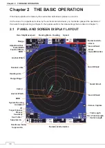


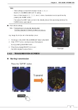


Chapter 2 THE BASIC OPERATION
41
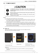
2.3 POWER ON/OFF
A malfunction may occur if the power in the ship is instantaneously
interrupted during operation of the radar. In the case, the power should be
turned on again.
When the display unit is turned off by the power drop, power supply to the
scanner unit also stops.
Make sure that the supply voltage to the display unit is stable, the power
should be turned on again.
Note:
z
Wait for about 2 seconds before turn on the power again.
z
Immediately after the radar is installed, at start of the system after it has not been used for a long
time, or after the magnetron is replaced, preheat the equipment in the standby state for 20 to 30
minutes before setting it into the transmit state.
z
If the preheating time is short, the magnetron causes sparks, resulting in its unstable oscillation.
Start transmission on a short-pulse range and change the range to the longer pulse ranges in turn. If
the transmission is unstable in the meantime, immediately place the system back into the standby
state and maintain it in the standby state for 5 to 10 minutes before restarting the operation. Repeat
these steps until the operation is stabilized.
Power on
(90 seconds preheat time is required for cold start, because of the Magnetron heater.)
After 90 seconds, anytime transmitting is possible.
Reference:
The radar cannot start transmission if you press the TX/PRF icon while the preheating time
is displayed.
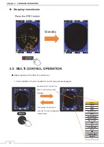
Press the STBY button
Opening screen
Preheating time display
(Preheating time : 90 seconds)
Содержание JMA-3400 Series
Страница 2: ......
Страница 23: ...WARNING LABEL MOUNTING POINT xxi NKE 2103 4 4HS 6 6HS SCANNER UNIT NCD 2364 DISPLAY UNIT ...
Страница 31: ...EQUIPMENT APPEARANCE xxix NKE 2043 SCANNER UNIT NKE 2063A AHS SCANNER UNIT ...
Страница 32: ...EQUIPMENT APPEARANCE xxx NKE 2103 4 4HS 6 6HS SCANNER UNIT ...
Страница 34: ...EQUIPMENT APPEARANCE xxxii Fuse ...
Страница 48: ......
Страница 51: ...Chapter 1 INSTALLATION 3 1 2 3 DIMENSIONAL DRAWING OF DISPLAY MOUNTING ...
Страница 53: ...Chapter 1 INSTALLATION 5 1 2 4 EXAMPLES OF DISPLAY MOUNTING Ŷ DESK TOP INSTALLATION Mounting Bracket ...
Страница 56: ...Chapter 1 INSTALLATION 8 FLUSH MOUNTING TEMPLATE Note Please note the paper size ...
Страница 85: ...Chapter 2 THE BASIC OPERATION 37 2 2 OPERATION UNIT ࢫࣆ ձ ղ ճ մ յ ն շ ո չ պ վ տ ւ ջ ռ ս ր ց ...
Страница 265: ...217 Chapter 13 SPECIFICATIONS Chapter 13 SPECIFICATIONS NKE 2063A AHS NKE 2043 NNKE 2103 6 6HS NKE 2103 4 4HS NCD 2364 ...
Страница 266: ...Chapter 13 SPECIFICATIONS 218 13 1 SCANNER DIMENSION 13 1 1 NKE 2043 ...
Страница 270: ...Chapter 13 SPECIFICATIONS 222 13 2 DISPLAY DIMENSION 13 2 1 NCD 2364 ...
Страница 283: ...235 Chapter 13 SPECIFICATIONS MEMO ...
Страница 293: ...APPENDIX A 10 MEMO ...
Страница 313: ......