


Chapter 1 INSTALLATION
14
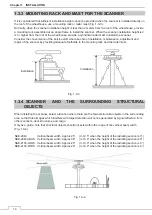
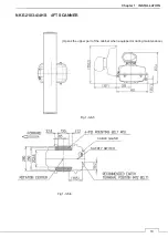
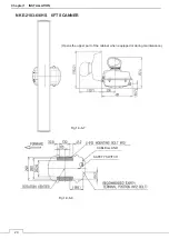
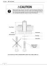
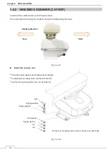
1.3.3 MOUNTING RACK AND MAST FOR THE SCANNER
If it is considered that sufficient installation height cannot be provided when the scanner is installed directly on
the roof of the wheelhouse, use a mounting rack or radar mast (Fig. 1-3-3).
Normally, when the scanner installation height is less than 2 meters from the roof of the wheelhouse, provide
a mounting rack assembled at an angle frame to install the scanner. When the scanner installation height is 2
m or higher from the roof of the wheelhouse, provide a cylindrical radar mast to install the scanner.
Consider the convenience of the service staff who take care of installation, maintenance, adjustment and
repair of the scanner by providing adequate footholds to the mounting rack and the radar mast.
Fig. 1-3-3
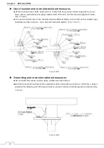
1.3.4
SCANNER AND THE SURROUNDING STRUCTURAL
OBJECTS
When installing the scanner, select a location where there are the fewest structural objects in the surrounding
area so that false images which interfere with target detection will not be generated by signal reflection from
other scanners, deck structures, and cargo.
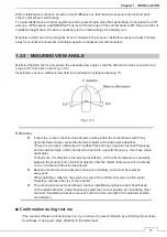
Only as a guide, note that structural objects should not exist within the range of the vertical beam width
(Fig. 1-3-4).
NKE-2043
Vertical beam width: Approx.25°
(+/-12.5° when the height of the radiating section is 0°)
NKE-2063A/AHS Vertical beam width: Approx.30°
(+/-15.0° when the height of the radiating section is 0°)
NKE-2103-4/4HS Vertical beam width: Approx.20°
(+/-10.0° when the height of the radiating section is 0°)
NKE-2103-6/6HS Vertical beam width: Approx.20°
(+/-10.0° when the height of the radiating section is 0°)
Fig. 1-3-4
Fig. 1-3-4
Installation
Installation
Содержание JMA-3400 Series
Страница 2: ......
Страница 23: ...WARNING LABEL MOUNTING POINT xxi NKE 2103 4 4HS 6 6HS SCANNER UNIT NCD 2364 DISPLAY UNIT ...
Страница 31: ...EQUIPMENT APPEARANCE xxix NKE 2043 SCANNER UNIT NKE 2063A AHS SCANNER UNIT ...
Страница 32: ...EQUIPMENT APPEARANCE xxx NKE 2103 4 4HS 6 6HS SCANNER UNIT ...
Страница 34: ...EQUIPMENT APPEARANCE xxxii Fuse ...
Страница 48: ......
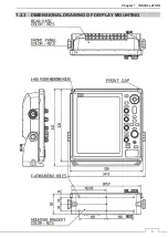
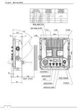
Страница 51: ...Chapter 1 INSTALLATION 3 1 2 3 DIMENSIONAL DRAWING OF DISPLAY MOUNTING ...
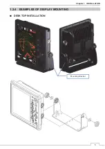
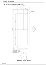
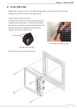
Страница 53: ...Chapter 1 INSTALLATION 5 1 2 4 EXAMPLES OF DISPLAY MOUNTING Ŷ DESK TOP INSTALLATION Mounting Bracket ...
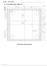
Страница 56: ...Chapter 1 INSTALLATION 8 FLUSH MOUNTING TEMPLATE Note Please note the paper size ...
Страница 85: ...Chapter 2 THE BASIC OPERATION 37 2 2 OPERATION UNIT ࢫࣆ ձ ղ ճ մ յ ն շ ո չ պ վ տ ւ ջ ռ ս ր ց ...
Страница 265: ...217 Chapter 13 SPECIFICATIONS Chapter 13 SPECIFICATIONS NKE 2063A AHS NKE 2043 NNKE 2103 6 6HS NKE 2103 4 4HS NCD 2364 ...
Страница 266: ...Chapter 13 SPECIFICATIONS 218 13 1 SCANNER DIMENSION 13 1 1 NKE 2043 ...
Страница 270: ...Chapter 13 SPECIFICATIONS 222 13 2 DISPLAY DIMENSION 13 2 1 NCD 2364 ...
Страница 283: ...235 Chapter 13 SPECIFICATIONS MEMO ...
Страница 293: ...APPENDIX A 10 MEMO ...
Страница 313: ......