background image

MacGregor Industries


80 GLIDER


Switch Identification: 


AIL D/R 

Aileron Dual Rate switch. 

TIME SW 

Trainer switch. 

ELE D/R 

Elevator Dual Rate switch. 

MOTO SW  Motor (Gear) switch. 

RUD D/R  Rudder Dual Rate switch. 

TIM KEY 

Timer key (bottom key). 

BTFL SW 

Butterfly (Mix/Hold) switch. 


Press the LIST key to return to the Function Menu.  Press the enter (ENT) key to return to the Information Display Screen. 

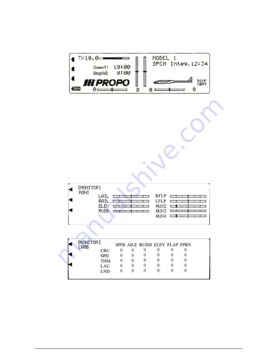
Servo Monitor


The Function Menu List is accessed from the Information Display Screen by pressing the LIST key.  From the Function 

Menu List, rotate the Scroll Bar to highlight the "MONITOR" menu choice and click the Scroll Bar. 


The Monitor gives a graphical representation in Bar Graph form of the movement of the servos as the controlling sticks, 

levers and switches are operated.  It is invaluable for showing how the various System and Function Mode adjustments will 

affect the servo response.  The channels are displayed in output order with channel 1 as the top left display, working down 

to channel 4 as the bottom left display and channel 5 as the top right display working down to channel 9 as the bottom right 

display.  As channels are allocated in System Mode - DeviceSEL, the name of the identity of the Bar Graph line changes to 

reflect the allocation.  This is very useful for identifying the correct servo position in the model.  The centre of the line 

represents servo neutral, and the ends of the line represent 150% travel from neutral.  The marks between the centre and 

the ends represent 50% and 100% travel from neutral.  To confirm the operating control allocation in System Mode - 

DeviceSEL, the selected stick, lever or switch can be operated while observing the display.  


A second display screen gives the current position, in numerical format, of all Digital Trim controls, for all Flight Modes.  


Please note that the display will show only the Flight Modes activated in System Mode - DeviceSEL. 


To toggle between the Bar Graph and Digital Trim screens, 

highlight the word MONI (or CAMB if previously 

selected) by rotating the Scroll Bar and click to toggle between MONI (Bar Graphs displayed) and CAMB (Digital Trim 

settings displayed). 


Press the LIST key to return to the Function Menu.  Press the enter (ENT) key to return to the Information Display Screen. 


Содержание PCM9XII

Страница 1: ...MacGregor Industries MACGREGOR INDUSTRIES Instruction Manual PCM9XII ...

Страница 2: ...Ltd wish to thank Horizon Hobbies for their permission to use sections of their XP 9303 Manuals when writing this PCM9XII Manual MacGregor Industries Ltd 2005 Canal Estate Langley Slough SL3 6EQ Phone 01753 549111 Fax 01753 546983 Email service macgregor co uk ...

Страница 3: ...Mixing 25 Gyro Gain 25 JR G490T Gyro Set up 26 Cyclic to Throttle Mix 27 Governor 29 Multipoint Program Mix 1 and 2 29 Standard Program Mix 3 to 6 31 Fail safe 33 Trainer 34 Timer 36 Servo Monitor 37 Throttle Cut 37 Helicopter Data Sheet 39 CHAPTER 3 Function Menu Aero Dual Rates Exponential 40 Servo Reverse 41 Sub Trim 41 Travel Adjust 42 Elevator to Flap Mix 42 Aileron to Rudder Mix 43 Throttle ...

Страница 4: ...MacGregor Industries This page is intentionally blank ...

Страница 5: ...at it is selected Rotate the Scroll Bar to the right to darken the screen or to the left to lighten the screen When the required setting is achieved click the Scroll Bar to exit the sub menu Of course if the change is taken too far the screen display cannot be seen No need to panic simply rotate the Scroll Bar or press the CLR clear key and the display will re appear If it does not switch off swit...

Страница 6: ...such as servo travel adjustment sub trim servo monitor etc that might be viewed or adjusted on the flying field To enter the Function Menu press the LIST key The Function Menu List is displayed Transmitter Layout SCROLL BAR INTERFACE IMPORTANT Rotate the Scroll Bar by resting the thumb on the bottom of the bar half on the bar and half on the bezel This will prevent accidental selections Click the ...

Страница 7: ...he allen key anticlockwise Adjust the stick length to your requirement and lock the stick in place by turning the grub screw clockwise Please note that optional coloured sticks and long short sticks are available from your Local Model Shop CONTROL STICK TENSION The stick tension may be adjusted to suit your preference To adjust the tension remove the RF Module NiCad battery and the back cover scre...

Страница 8: ...ger will rise in temperature This is normal and should not cause concern If you have any worries about any of the charging equipment please seek expert advice Please be sure to use the correct charge rate for your battery pack any battery over 1000 mAH should be charged at 120 mA SYSTEM CONTENTS subject to change 1 x NET 229ES PCM9XII Transmitter 1 x R900 ABC W Receiver 4 x NES 811 high performanc...

Страница 9: ...y of a set up for a model that has been completed refined and tested The backup allows experimentation with the current set up knowing that the original can be easily restored To select a new Model Memory highlight the current model number by rotating the Scroll Bar and click to bring up the sub menu A browse box of the available Model Memories appears Rotate the Scroll Bar to select the new Model...

Страница 10: ...ted will be displayed on the Information Display Screen To input a Model Name move the cursor small black triangle by rotating the Scroll Bar until it points to the position of the first character of the name and click to bring up the sub menu A browse box of all possible characters appears Rotate the Scroll Bar to highlight the required character and click to select The character appears on the s...

Страница 11: ...M start with the transmitter switched off Press the ENT Enter key and while holding it down switch the transmitter on The System Menu List is displayed Rotate the Scroll Bar to highlight the MODULAT menu choice and click it to bring up the sub menu The Modulation Select screen appears with a display of the current modulation type The PCM9XII system supports three types of modulation PCM types S an...

Страница 12: ...Data is sent with a Progress Indicator on the right of the screen counting up to 100 A further screen warning End OK is given to indicate that the receive transmitter should display the same message Data may be sent repeatedly if required To prepare to receive data highlight the TRANSMIT RECEIVE menu choice by rotating the Scroll Bar and click to toggle between TRANSMIT and RECEIVE Leave the selec...

Страница 13: ...troke Trim select the primary channel adjacent to Type by rotating the Scroll Bar and click on it to toggle between L S T and Normal The black indicator square moves between the bottom of the box NORMAL to the top of the box L S T to indicate the current selection The selection toggles between the NORMAL and L S T positions with each click Press the LIST key to return to the System Menu List Press...

Страница 14: ... choices Press the LIST key to return to the System Menu List Press the enter ENT key to return to the Information Display Screen Device Select Aero To access the System Menu List SYSTEM M start with the transmitter switched off Press the ENT Enter key and while holding it down switch the transmitter on The System Menu List is displayed Rotate the Scroll Bar to highlight the DeviceSEL menu choice ...

Страница 15: ...elected to operate the Auxiliary Channels The activation switches displayed in the browse box will depend on the channel output choices To select an Auxiliary Channel operating switch lever highlight the Auxiliary Channel reference GEAR FLAP AUX2 AUX3 or AUX4 by rotating the Scroll Bar and click on it to bring up the sub menu A box of the available operating devices shows Select the required contr...

Страница 16: ...t the appropriate ACT INH SYS GYRO in the bottom line to the right of OUT by rotating the Scroll Bar and click on it to swap between the choices Press the LIST key to return to the System Menu List Press the enter ENT key to return to the Information Display Screen Device Select Glider Mode To access the System Menu List SYSTEM M start with the transmitter switched off Press the ENT Enter key and ...

Страница 17: ...t Mode activation switch by rotating the Scroll Bar and click on it to activate the selection To inhibit the SPEED Flight Mode select and click on INH Switch Identification AIL D R Aileron Dual Rate switch FMOD SW Flight Mode switch ELE D R Elevator Dual Rate switch AUX4 SW AUX2 FLAP switch RUD D R Rudder Dual Rate switch MOTO SW Motor Gear switch BTFL SW Butterfly Mix Hold switch The TRIM FM sele...

Страница 18: ...ormation Display Screen Wing Type Aero To access the System Menu List SYSTEM M start with the transmitter switched off Press the ENT Enter key and while holding it down switch the transmitter on The System Menu List is displayed Rotate the Scroll Bar to highlight the Wing TYPE menu choice and click to bring up the sub menu The screen will appear as below but with minor deviations according to prev...

Страница 19: ...ht Wing to the left of NORMAL by rotating the Scroll Bar and click on it to bring up the sub menu Select the required Wing Type by rotating the Scroll Bar and click on it to exit the sub menu The selected Wing Type is displayed To select the V Tail system highlight INH to the right of V TAIL by rotating the Scroll Bar and click on it to toggle the choice between INH V Tail inhibited and ACT V Tail...

Страница 20: ...MATE below TWIN E Highlight that INH by rotating the Scroll Bar and click on it to toggle between INH and ACT When Trim inhibited INH is selected the Throttle Trim input will apply only to the Throttle servo When Trim active ACT is selected the Throttle Trim input will be applied to both servos If FLAP or AUX3 are selected as the Mate an extra menu choice appears in line with AUXT If enabled the a...

Страница 21: ...ypes of Cyclic Collective Pitch Mixing CCPM The Normal mode 1sNORM uses separate servos for the Aileron Elevator and Pitch inputs and the other modes electronically mix the stick inputs to move the servos to give the required helicopter response Further details are given in the Helicopter Function Menu chapter The five pre programmed versions of CCPM are 4 servo 90 3 servo 90 3 servo 140 3 servo 1...

Страница 22: ... to the System Menu List Press the enter ENT key to return to the Information Display Screen Stick Direction To access the System Menu List SYSTEM M start with the transmitter switched off Press the ENT Enter key and while holding it down switch the transmitter on The System Menu List is displayed Rotate the Scroll Bar to highlight the STICK Dir menu choice and click to bring up the sub menu The T...

Страница 23: ...it to bring up the sub menu choices The highlighting is surrounded by a box to indicate that it is selected The right hand side of the screen displays a graphical representation of the response curve Rotate the Scroll Bar to alter the setting With the control stick at neutral the figures for both sides of neutral change together If the control stick for the channel being adjusted is moved from neu...

Страница 24: ...equired channel by rotating the Scroll Bar and click on it to toggle between normal and reversed The black direction indicator square moves between the top of the box reversed and the bottom of the box normal to indicate the current selection When the required setting is achieved click the Scroll Bar to exit the sub menu Note when CCPM is selected the CCPM channels will be re named CH2 CH3 CH6 CH8...

Страница 25: ...e movement so that the travel of both servos is adjusted together To set a travel value highlight the required figure by rotating the Scroll Bar and click on it to bring up the sub menu Pairs of figures are surrounded by a box to indicate that they are selected Move the control stick to swap between the right left up down figures and rotate the Scroll Bar to alter the setting To return the figures...

Страница 26: ...old can be automatically inhibited by the Throttle stick position and a transition delay of up to 2 seconds can be introduced to slow the Throttle response when the hold is deactivated To activate Throttle Hold click the Scroll Bar to toggle between INH inhibited and ACT active The screen will appear as above with minor variations depending on previous settings Notice that ON appears adjacent to T...

Страница 27: ...ar response the figures move together and with a curved response the output follows the non linear curve To select the Throttle curve screen highlight NORM or previous curve at the top left of the screen by rotating the Scroll Bar and click on it to bring up a browse box of the available curves Rotate the Scroll Bar to highlight the required curve and click to select The new curve appears in the s...

Страница 28: ... Servo output position with zero being at one extreme 50 being the centre and 100 being the other extreme With a linear response the figures move together and with a curved response the output follows the non linear curve To select a Pitch curve display highlight NORM or previous curve at the top left of the screen by rotating the Scroll Bar and click on it to bring up a browse box of the availabl...

Страница 29: ...g Note that this function should not be used with a gyro in heading hold mode Revolution Mix Set up Set up the helicopter so that it will hover with the Tail Rotor Trim centred Establish the helicopter into a stable hover then slowly increase the Throttle to initiate a steady climb The body of the helicopter will move in the opposite direction to the main rotor rotation Increase the U up setting u...

Страница 30: ...M ST 1 etc by rotating the Scroll Bar and click on it to bring up a browse box of the gain choices Highlight the required gain Pos 0 Pos 1 or Pos 2 and click to exit the sub menu The chosen gain is used for the selected Flight Mode Please note that the ST 3 and ST 4 Flight Modes will only appear if F MODE EXTRA has been enabled in System Mode DeviceSEL Hold will only appear if THRO Hold has been a...

Страница 31: ...osition Cyclic to Throttle Mixing The Function Menu List is accessed from the Information Display Screen by pressing the LIST key From the Function Menu List rotate the Scroll Bar to highlight the MIX THRO menu choice and click the Scroll Bar The PCM9XII s Cyclic to Throttle function is designed to correct any under speeding or over speeding of the main rotor due to load changes placed upon the en...

Страница 32: ...MOD EXTRA has been enabled in System Mode DeviceSEL Switch Identification ON Mix permanently active NRM Mix active in Flight Mode Normal ST1 Mix active in Flight Mode 1 ST2 Mix active in Flight Mode 2 ST3 Mix active in Flight Mode 3 Appears when F MOD EXTRA is enabled in System Mode DeviceSEL ST4 Mix active in Flight Mode 4 Appears when F MOD EXTRA is enabled in System Mode DeviceSEL To set a mix ...

Страница 33: ...Function Menu Press the enter ENT key to return to the Information Display Screen Multipoint Program Mixes1 and 2 The Function Menu List is accessed from the Information Display Screen by pressing the LIST key From the Function Menu List rotate the Scroll Bar to highlight the PROG Mix menu choice and click the Scroll Bar Programmable mixes enable any channel to be mixed to any channel including it...

Страница 34: ...RO or previously selected Master channel by rotating the Scroll Bar and click on it to bring up the sub menu A browse box of the available Master channels appears with a heading of Mast to indicate that the Master channel is being selected Rotate the Scroll Bar to select the required channel and click on it to exit the sub menu To exit without making changes select and click on the CANCEL menu cho...

Страница 35: ...ick on them twice once to activate and once to exit The hidden value will appear and the mix point will become active Press the LIST key to return to the Function Menu Press the enter ENT key to return to the Information Display Screen Program Mixes3 to 6 The Function Menu List is accessed from the Information Display Screen by pressing the LIST key From the Function Menu List rotate the Scroll Ba...

Страница 36: ... mix GEAR Gear channel ELE Elevator channel incl trim PIT Pitch channel AUX1 PIT Pitch channel Origin mix AUX2 Auxiliary 2 channel AIL Aileron channel incl trim AUX3 Auxiliary 3 channel RUD Rudder channel incl trim AUX4 Auxiliary 4 Channel TIMT The timer switch Slave Channel Identification THRO Throttle channel PIT Pitch channel AILE Aileron channel AUX2 Auxiliary 2 channel ELEV Elevator channel A...

Страница 37: ...lay the Fail Safe system can be programmed to continue to hold the servos or to move them to a pre determined Fail Safe position Please note that the AUX4 channel cannot accept a Fail Safe position and will always hold its last known good position in a Fail Safe situation S PCM Modulation All channels can be HOLD or individual channels can take a pre selected position The fail safe time delay is f...

Страница 38: ...ctions are controlled by either the Master transmitter or the Slave and the Programmable Function Trainer where one or more of the four primary control functions may be assigned to the Slave individually With the Programmable Function Trainer all set up parameters such as Servo Reverse Travel Adjust and any mixes are taken from the Master transmitter The PCM9XII also has a special Slave mode where...

Страница 39: ...s with each click When Slave is selected control of that channel is transferred to the Slave transmitter as the Trainer switch is operated Repeat the selection for all channels that are to be transferred Notice that when one or more channels are selected as Slave the screen changes from NORMAL T to PROGRAM T to indicate the current Trainer mode To reset the Trainer system to normal press the clear...

Страница 40: ...10 to zero seconds At zero there will be a continuous tone for 1 second and then the timer will begin counting up with a indication to the left of the time display When used as the Stopwatch the timer will count up to 59 minutes 59 seconds and then re start from zero To reset the internal timer select the time figure below INTEG T by rotating the Scroll Bar Push CLR 0 00 appears on the display Pre...

Страница 41: ... Bar Graphs displayed and TRIM Digital Trim settings displayed Press the LIST key to return to the Function Menu Press the enter ENT key to return to the Information Display Screen Throttle Cut The Function Menu List is accessed from the Information Display Screen by pressing the LIST key From the Function Menu List rotate the Scroll Bar to highlight the THRO TRIM menu choice and click the Scroll ...

Страница 42: ...her than decrease it Please note that if the Throttle Cut feature is enabled the Intelligent Trim cannot be activated If you wish to use Intelligent Throttle Trim you must first inhibit the Throttle Cut facility To enable Intelligent Throttle Trim select and click on INH below Memory TRIM Successive clicks will toggle the Intelligent Memory Trim between active ACT and inhibited INH To operate the ...

Страница 43: ...MacGregor Industries 39 HELI ...

Страница 44: ... the response curve The selected rate can be enabled by the rate switches Pos 0 and Pos 1 or by any of the Flight Modes Pos 0 and Pos 1 and Pos 2 Please note that the screen display will depend on the selections made in System Mode DeviceSEL The screen will display Pos 0 and Pos 1 when the rate is selected by the Dual Rate switches and F M 0 F M 1 and F M 2 when the rate is selected by the Flight ...

Страница 45: ...ersed and the bottom of the box normal to indicate the current selection When the required setting is achieved click the Scroll Bar to exit the sub menu Press the LIST key to return to the Function Menu Press the enter ENT key to return to the Information Display Screen Sub Trim The Function Menu List is accessed from the Information Display Screen by pressing the LIST key From the Function Menu L...

Страница 46: ...light Mode switches will only show when Flight Modes are enabled in System Mode DeviceSEL The Elevator to Flap mix moves the Flaps in addition to the Elevator to give more pitch authority Two different Elevator to Flap settings may be selected with independent up or down travel adjustment The required mix can be selected with the Flight Modes with various switches or by a Throttle stick position M...

Страница 47: ... surrounded by a box to indicate that it is selected Rotate the Scroll Bar to alter the setting To return the figures to the default of 0 press the clear CLR key at the left hand side of the screen When the required setting is achieved click the Scroll Bar to exit the sub menu To select an activation switch highlight the required switch by rotating the Scroll Bar and click on it to toggle between ...

Страница 48: ...ystem Mode DeviceSEL To select an activation switch highlight SW SELECT by rotating the Scroll Bar and click on it to bring up the sub menu A browse box will appear containing the available switches Highlight the required switch by rotating the Scroll Bar and click on it to toggle between POS0 and POS1 The black indicator square moves between the bottom of the box POS0 to the top of the box POS1 t...

Страница 49: ...ccessed from the Information Display Screen by pressing the LIST key From the Function Menu List rotate the Scroll Bar to highlight the FLAP SYS menu choice and click the Scroll Bar Three switch controlled Flap positions Elevator compensation for each Flap position Throttle override for aborted landings Programmable Flap deployment delay Flight Mode controlled Flap deployment The NORM Mid and Land...

Страница 50: ...ith inadequate flying speed when landing the model may stall into the ground For this reason we recommend that high values of Throttle are set for initial experiments and that flying speed is increased before advancing the Throttle above the chosen threshold to retract the Flaps To set a transition delay highlight Delay on the bottom right of the screen by rotating the Scroll Bar and click on it t...

Страница 51: ...ght up L D left down or L U left up by rotating the Scroll Bar and click on it to bring up the sub menu The figure is surrounded by a box to indicate that it is selected Rotate the Scroll Bar to alter the setting To return the figures to the default of 100 press the clear CLR key at the left hand side of the screen Figures between zero and 125 may be set When the required setting is achieved click...

Страница 52: ...ed the central gain values are used over the entire stick movement range To set a Gyro gain highlight the chosen central gain figure 0 1 or 2 to the right of CEN screen choice by rotating the Scroll Bar and click on it to activate The figure is surrounded by a box to indicate that it is selected Rotate the Scroll Bar to set the Gyro gain gain Values between zero and 100 may be entered To set the g...

Страница 53: ... the required setting is achieved click the Scroll Bar to exit the sub menu To select an activation switch highlight the required switch by rotating the Scroll Bar and click on it to toggle between POS0 and POS1 The black indicator square moves between the bottom of the box POS0 to the top of the box POS1 to indicate the current selection The selection toggles between the POS0 and POS1 positions w...

Страница 54: ... When Pos0 shows the position 0 settings may be adjusted and when Pos1 shows the position 1 settings may be adjusted To set a servo speed highlight the word NORM adjacent to the channel of the servo to be adjusted by rotating the Scroll Bar and click on it to bring up the sub menu The figure is surrounded by a box to indicate that it is selected Rotate the Scroll Bar to alter the setting Speeds be...

Страница 55: ...l other switches are ignored and the Pos1 values are used The channel providing the signal for the mix is known as the Master Mast channel and the channel being controlled is the Slave Slav channel When using the Throttle channel as the Master any trim input is automatically passed to the Slave With all other channels Master input channel trim movements are ignored Master channel modifiers Travel ...

Страница 56: ...s If Aileron is selected as a Slave the mix causes the Aileron servos to move in opposite directions like Ailerons To select an activation switch highlight SW SELECT by rotating the Scroll Bar and click on it to bring up the sub menu A browse box will appear containing the available switches Highlight the required switch by rotating the Scroll Bar and click on it to toggle between 0N and OFF The b...

Страница 57: ...form a particular function the mix can be to the function rather than to an individual servo Two different mix values may be set Pos0 and Pos1 between 125 with individual values for each side of neutral The mix can be permanently active or enabled and disabled by the Flight Modes and other switches or by a pre selected Throttle stick position When the mix is activated by a switch or Throttle stick...

Страница 58: ...servos move up and down in the same direction like Flaps If Aileron is selected as a Slave the mix causes the Aileron servos to move in opposite directions like Ailerons To set a mix value highlight the required mix position Pos0 or Pos1 by rotating the Scroll Bar and click on it to bring up the sub menu The figures are surrounded by a box to indicate that they are selected Move the Master stick s...

Страница 59: ...ction Menu when SPCM or ZPCM modulation types are selected in System Mode MODULAT The Function Menu List is accessed from the Information Display Screen by pressing the LIST key From the Function Menu List rotate the Scroll Bar to highlight the Fail Safe menu choice and click the Scroll Bar In the face of interference PCM receivers hold the servos at their last known good position If the interfere...

Страница 60: ...ST key to return to the Function Menu Press the enter ENT key to return to the Information Display Screen Trainer The Function Menu List is accessed from the Information Display Screen by pressing the LIST key From the Function Menu List rotate the Scroll Bar to highlight the Trainer menu choice and click the Scroll Bar The PCM9XII transmitter provides two separate types of trainer system the Norm...

Страница 61: ...e moves between the bottom of the box MAST to the top of the box SLAV to indicate the current selection The selection toggles between the MAST and SLAV positions with each click When Slave is selected control of that channel is transferred to the Slave transmitter as the Trainer switch is operated Repeat the selection for all channels that are to be transferred Notice that when one or more channel...

Страница 62: ...to zero seconds At zero there will be a continuous tone for 1 second and then the timer will begin counting up with a indication to the left of the time display When used as the Stopwatch the timer will count up to 59 minutes 59 seconds and then re start from zero To reset the internal timer select the time figure below INTEG T by rotating the Scroll Bar Push CLR 0 00 appears on the display Press ...

Страница 63: ... indicator changes between MONI for the Servo Monitor screen and TRIM for the Digital Trim display When Flight Modes are active and the trim settings are assigned to each Flight Mode the TRIM list shows the trim settings for each Flight Mode Press the LIST key to return to the Function Menu Press the enter ENT key to return to the Information Display Screen Throttle Cut The Function Menu List is a...

Страница 64: ...een returns the setting point to the default of 12 Please note that the position set is an absolute servo position If the Throttle Digital Trim is set to a value below the set figure the CUT switch will increase the Throttle position rather than decrease it Please note that if the Throttle Cut feature is enabled the Intelligent Trim cannot be activated If you wish to use Intelligent Throttle Trim ...

Страница 65: ...MacGregor Industries 61 AERO ...

Страница 66: ...d not the Throttle Spoiler R900 Receiver Channel Marking Servo Allocation THRO Throttle Left Aileron LAIL AILE Aileron Right Aileron RAIL ELEV Elevator Elevator ELEV RUDD Rudder Rudder RUDD GEAR Gear Motor Control MOTO Right Flap RFLP when Dual Flap is selected AUX1 Flap Flap FLAP Left Flap LFLP when Dual Flap is selected AUX2 Free Allocation AUX3 Free Allocation AUX4 Free Allocation DualRates Exp...

Страница 67: ...se curve Rotate the Scroll Bar to alter the setting With the control stick at neutral the figures for both sides of neutral change together To change the figures for each side of neutral independently move the control stick to the side to be adjusted Only one figure is highlighted and changed To return the figures to the default of linear LIN press the clear CLR key at the left hand side of the sc...

Страница 68: ...ate the Scroll Bar to alter the setting To return the figures to the default of zero press the clear CLR key at the left hand side of the screen When the required setting is achieved click the Scroll Bar to exit the sub menu Channel Identification LAIL Left Aileron receiver channel 1 marked THRO on receiver case RAIL Right Aileron receiver channel 2 marked AILE on receiver case ELEV Elevator recei...

Страница 69: ...es activated in System Mode DeviceSEL To set a mix value and offset highlight the required figure by rotating the Scroll Bar and click on it to bring up the sub menu The figure is surrounded by a box to indicate that it is selected Rotate the Scroll Bar to alter the setting To return the figures to the default of 0 press the clear CLR key at the left hand side of the screen When the required setti...

Страница 70: ...d the top of the box POS1 to indicate the selection When the required setting is achieved click the Scroll Bar to exit the sub menu Multiple switches may be used to select the Pos1 values but any switch in the POS1 position will then force the Pos1 values to be used Note that when a switch Flight Mode is selected to change between the mix values the switch indicator to the right of AIL FLP M on th...

Страница 71: ...play will only show the Flight Modes activated in System Mode DeviceSEL To set a delay value highlight the required figure by rotating the Scroll Bar and click on it to bring up the sub menu The figure is surrounded by a box to indicate that it is selected Rotate the Scroll Bar to alter the setting To return the figure to the default of 0 press the clear CLR key at the left hand side of the screen...

Страница 72: ...ing up the sub menu The figure is surrounded by a box to indicate that it is selected Rotate the Scroll Bar to alter the setting To return the figures to the default of 0 press the clear CLR key at the left hand side of the screen When the required setting is achieved click the Scroll Bar to exit the sub menu To set a Flap lever offset value highlight Offset by rotating the Scroll Bar and click on...

Страница 73: ...l Bar and click on it to bring up the sub menu The figure is surrounded by a box to indicate that it is selected Rotate the Scroll Bar to alter the setting To return the figures to the default of 0 press the clear CLR key at the left hand side of the screen When the required setting is achieved click the Scroll Bar to exit the sub menu To set a SPOI ELEV 0 ELEV 1 Elevator movement mix value highli...

Страница 74: ...unction Menu List is accessed from the Information Display Screen by pressing the LIST key From the Function Menu List rotate the Scroll Bar to highlight the FLAP RATE menu choice and click the Scroll Bar The Flap rate set up enables multiple Flap travel adjustments to be set with a separate rate for each of the five Flight Modes With this system the Flap AUX3 lever is used to control the Flap ser...

Страница 75: ...tween the bottom of the box OFF and the top of the box ON to indicate the current selection The selection toggles between the ON and OFF positions with each click Note that when a switch Flight Mode is selected to enable the hold facility the switch indicator to the right of MOTO HOLD on the top left of the screen changes from ON to OFF as the activation switch is moved Switch Identification CRU C...

Страница 76: ...position with zero being at one extreme 50 being the centre and 100 being the other extreme The OUT figure represents the Slave output channel position with 100 being at one extreme zero being the centre and 100 being the other extreme With a linear response the figures move together and with a curved response the output follows the non linear curve Please note that the actual Master and Slave cha...

Страница 77: ...t of the screen are replaced with OFF as the activation switch is moved Switch Identification CRU Cruise Flight Mode Appears when Flight Modes have been activated in System Mode DeviceSEL SPD Speed Flight Mode Appears when SPEED Flight Mode has been activated in System Mode DeviceSEL THM Thermal Flight Mode Appears when SPEED Flight Mode has been activated in System Mode DeviceSEL LAU Launch Fligh...

Страница 78: ... any trim input is automatically passed to the Slave With all other channels Master input channel trim movements are ignored Master channel modifiers Travel Adjustments Dual Rates etc are automatically passed to the Slave channel As an example if the Master channel travel is reduced by 50 by the Dual Rate feature the Slave now only moves by 50 The four primary channels have additional special Mast...

Страница 79: ...ck the Scroll Bar to exit the sub menu Note that when the mix is permanently on any entries for Pos1 position 1 are ignored To set an offset value highlight Offset by rotating the Scroll Bar and click on it to bring up the sub menu The figure is surrounded by a box to indicate that it is selected Rotate the Scroll Bar to alter the setting To return the figures to the default of 0 press the clear C...

Страница 80: ...il Safe with each click As each channel is selected for Fail Safe any previously stored Fail Safe position will be displayed Figures between approximately 170 will show with 170 representing full servo deflection in one direction 170 representing full servo deflection in the other direction and zero representing the servo at neutral Move through the channels by rotating the Scroll Bar to select ei...

Страница 81: ...ller jack The Slave Transmitter remains switched OFF Although the screen lights the transmitter does not transmit The Slave Transmitter must contain a charged battery even though it remains switched off The Slave settings must be identical to the Master for the Normal Trainer System The Slave settings must be reset use Slave mode on PCM9XII for the Programmable Function Trainer System The Trainer ...

Страница 82: ...ing that to continue with the set up the DSC lead should be connected and the transmitter switched off The transmitter should remain turned off when used as a Slave as only the encoder section is required Inserting the DSC lead switches on only the required parts of the transmitter In Slave mode the modulation is automatically set to PPM and all channels are automatically reset to default values r...

Страница 83: ...he Scroll Bar to exit the sub menu To reset the time to the default of 10 minutes press the clear CLR key to the left of the Information Display To set TIMER 2 as Stopwatch highlight INH adjacent to TIMER 2 by rotating the Scroll Bar and click on it to bring up the sub menu A browse box of the available modes appears Rotate the Scroll Bar to select the STOP W choice and click on it to exit the sub...

Страница 84: ...nd channel 5 as the top right display working down to channel 9 as the bottom right display As channels are allocated in System Mode DeviceSEL the name of the identity of the Bar Graph line changes to reflect the allocation This is very useful for identifying the correct servo position in the model The centre of the line represents servo neutral and the ends of the line represent 150 travel from n...

Страница 85: ...MacGregor Industries 81 GLIDER ...

Страница 86: ...MacGregor Industries This page is intentionally blank ...

Страница 87: ...MacGregor Industries This page is intentionally blank ...

Страница 88: ...E OE Please note that while every effort has been taken to ensure the accuracy of the information contained in this booklet errors may occur MacGregor Industries Limited accept no responsibility for losses or damage caused ...

Отзывы: