


P5417009-rev.6
61
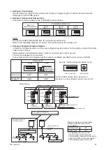
Figure 7.1 Layout for Electrical Wiring Connection (
Heat Recovery System)
TB1
Main Switch
Main Switch
Main Switch
TB1
TB2
L1 L2 L3
1 2 3 4
TB2
1 2 3 4
TB1
L1 L2 L3
1 2 A B
TB2
1 2 A B
TB2
TB1
L1 L2 N
L1 L2 N
L1 L2 N
L1 L2 N
L1 L2 N
No. 0
Indoor Unit
No. 1
Indoor Unit
Distribution Box or Pull Box
Distribution Box or Pull Box
Distribution Box or Pull Box
Distribution Box or Pull Box
Outdoor Unit A (Main)
Ground
Ground
Outdoor Unit B (Sub)
Controller
Cable
TB1
1 2 A B
TB2
No. 2
Indoor Unit
TB1
1 2 A B
TB2
No. 3
Indoor Unit
TB1
1 2 A B
TB2
No. 4
Indoor Unit
Wired
Controller
Controller
Cable
Wired
Controller
Controller
Cable
Wired
Controller
Controller
Cable
Wired
Controller
Controller
Cable
Wired
Controller
Indoor Unit Group
For Cooling Operation Only
1 2 3 4
Change-Over Box 1
TB2
TB1
1 2 3 4
Change-Over Box 2
TB2
TB1
1 2 3 4
Change-Over Box 3
TB2
TB1
1
208/230V 60Hz
TB : Terminal Block
PCB : Printed Circuit Board
: Field Wiring
: Communication Line
DC5V (Non-Pole Communication H-LINK System)
: Field-Supplied
: Optional Accessory
S
S
S
3
208/230V 60Hz
460V
60Hz
3
208/230V 60Hz
460V
60Hz
GFCI
GFCI
GFCI
GFCI
GFCI
GFCI
L
1
R
L
2
S
L
1
R
L
2
S
L
1
R
L
2
S
Содержание YVAHR072B32S
Страница 2: ......
Страница 88: ...P5417009 rev 6 Code No LIT 12012492 Revised February 2019 2017 Johnson Controls Inc ...


