


P5417009-rev.6
57
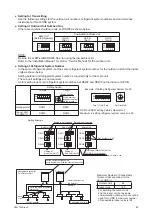
7.3 Electrical Wiring for Outdoor Unit
Connect the electrical wiring according to the following figure:
(1) Connect the power supply wires to L1, L2, and L3 for the three-phase power supply on the terminal
block TB1 and ground wiring to the terminal in the electrical control box.
(2) Connect the communication cables between the outdoor and indoor units to the TB2 terminals 1 and 2
on the PCB1. As for the communication cables between outdoor units in the same refrigerant system,
connect them to the TB2 terminals 3 and 4 on the PCB1. When shielded cable is applied (M4), secure
properly and terminate cable shield as required per Johnson Controls guidelines. Plenum and riser
ratings for communication cables must be considered per application and local code. Communication
cable must be a minimum of AWG18 (0.82mm
2
), 2-Conductor, Stranded Copper.
(3) Insert the communication cables into the PVC tube “VW-1 600V” (Accessory) to separate from the
power supply wirings and the communication cables in the outdoor unit. Local codes need to be
followed.
Then, tighten both ends of the PVC tubing with the cable bands (accessory) in order to secure the
PVC tubing to the communication cables.
When the rated voltage of the communication cables (local code) are 600V or more, it is not required
to insert them into the PVC tube “VW-1 600V” (accessory).
(4) Tighten screws for the terminal block according to the following table.
Required Tightening Torque
Size
Tightening Torque
M3.5
0.5 to 0.7
ft∙lbs
(0.7 to 0.9
N∙m)
M5
1.5 to 1.8
ft∙lbs
(2.0 to 2.4
N∙m)
M6
3.0 to 3.7
ft∙lbs
(4.0 to 5.0
N∙m)
M8
6.6 to 8.1
ft∙lbs
(9.0 to 11.0
N∙m)
M10
13.3 to 17.0
ft∙lbs
(18.0 to 23.0
N∙m)
Содержание YVAHR072B32S
Страница 2: ......
Страница 88: ...P5417009 rev 6 Code No LIT 12012492 Revised February 2019 2017 Johnson Controls Inc ...


