background image


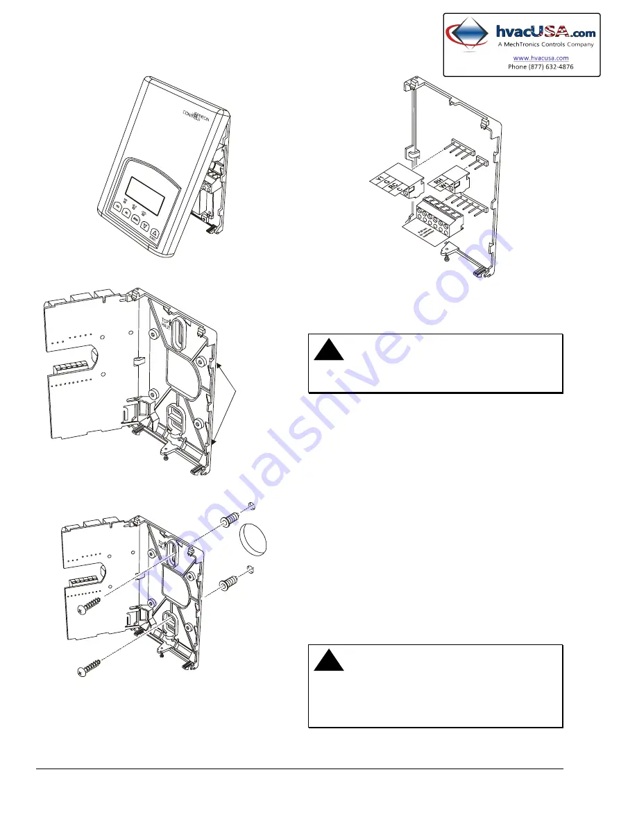
Figure 1: Removing the Thermostat Cover 

PCB

Locking Tabs


Figure 2: Opening the Thermostat PCB 


Figure 3: Mounting the Thermostat Base 


Figure 4: Removing the Terminal Blocks 

Wiring 

!

  CAUTION:  Risk of Electrical Shock.


Disconnect power supply before making electrical 
connections to avoid electrical shock.


Note: 

When replacing an existing thermostat, 

remove and label wires to identify terminal 
designations. When replacing a T600HCN-1 
thermostat, simply remove the terminal blocks and 
reinsert onto the new thermostat. 

To wire the thermostat: 

1.  Strip each wire 1/4 in. (6.35 mm) and connect to 

the appropriate terminal according to the wiring 
diagram (see Figure 5). 

2.  Gently push excess wire back into wall, plug the 

wall hole with fireproof material to prevent drafts 
from affecting ambient temperature readings, and 
install screw terminal blocks back onto the PCB. 

3.  Reattach the thermostat cover to the installed 

base (top side first) and install the security screw 
on the bottom. 

!

  CAUTION:  Risk of Property Damage. 

Do not apply power to the system before checking 
all wiring connections. Short circuited or improperly 
connected wires may result in permanent damage to 
the equipment. 


2    

T600HCN-1 Non-Programmable Thermostat Installation Instructions 

Содержание T600HCN-1

Страница 1: ...the thermostat cover see Figure 1 2 Unlock the Printed Circuit Board PCB by carefully pressing the locking tabs to the right see Figure 2 Open the thermostat s PCB to the left 3 Pull out approximatel...

Страница 2: ...e the thermostat 1 Strip each wire 1 4 in 6 35 mm and connect to the appropriate terminal according to the wiring diagram see Figure 5 2 Gently push excess wire back into wall plug the wall hole with...

Страница 3: ...24 VAC from equipment transformer 24 VAC common from equipment transformer 24 VAC for heating stage Configurable digital input Configurable digital input Remote room sensor Sensor common Outdoor air s...

Страница 4: ...uring normal thermostat operation The menu continually scrolls through the following parameters see Figure 6 Room Temperature System Mode Schedule Status Occupied Unoccupied see Note Outdoor Temperatu...

Страница 5: ...Maximum Cooling Cycles per Hour Cool cph Sets the Minimum Heating Cooling Deadband Default 2 0 F 1 1 C See Setting the Heating Cooling Deadband Deadband Determines how the Fan Activates in Response to...

Страница 6: ...nfigure Digital Input 2 or NO to advance to the keypad lockout setup prompt 4 Use the UP DOWN arrow keys to locate the desired function for the Digital Input 2 Press YES to select the desired function...

Страница 7: ...ows the minimum cooling setpoint prompt See the Setting the Minimum Cooling Setpoint Cool min section for instructions Setting the Minimum Cooling Setpoint Cool min The minimum cooling setpoint establ...

Страница 8: ...hes the minimum difference between the heating and cooling setpoints The range is adjustable from 2 to 4 F 1 to 2 C To change the minimum deadband between the heating and cooling setpoints while in th...

Страница 9: ...the display Press YES to enter the outdoor sensor calibration menu 2 Use the UP DOWN arrow keys to adjust the correction that should be applied to the sensor reading Press YES to store the offset The...

Страница 10: ...de schedule prompt only appears when the thermostat is in the unoccupied state This menu selection gives the user the option of overriding the unoccupied setpoints with the occupied setpoints for the...

Страница 11: ...et prompt appears in the display it may be the first prompt Press YES to enter temperature setting menu Press YES to change occupied cooling setpoint Press NO to advance to occupied heating setpoint m...

Страница 12: ...rn to the Status Display Menu or NO to return to the fan mode selection menu Setting Permanent Hold Note Displayed only if Digital Input DI1 or DI2 is configured for remote NSB This menu is used to se...

Страница 13: ...d to comply with the limits for a Class A digital device and verified to Class B pursuant to Part 15 of FCC Rules These limits are designed to provide reasonable protection against harmful interferenc...

Отзывы: