40
single-phase pump, special parameters of the inverter shall be set as
follows:
●
W hen the output is connected to the single-phase pump and the system
is powered on, the inverter "parameter setting" interface needs to be entered.
The "output selection" of the inverter is modified to "1" (" 0 "represents the
three-phase inverter output," 1 "represents the single-phase inverter
output).After modification, the inverter must be switched off and powered on
again. For specific modification steps, please refer to the chapters of “8.3.2.2
DSP Parameter Setting” and “8.3.4 Parameter Setting”.
●
After power on and restart, change "Debug mode" to "4".Please refer to
the section "8.3.2.2 DSP Parameter Setting" and "8.3.4 Parameter Setting"
for specific modification steps.
Note
!
When the inverter output load is connected to the si ngle-phase pump for the
first time, or when the wiring of single-phase pump is changed, the
"debugging mode" must be modified to "4" to test the motor parameters. After
the first motor parameter detection is successful, there is no need to conduct
motor parameter detection again in subsequent operations if the load is not
changed.
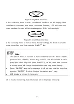
Long press the "ON/OFF" key ON the inverter panel for 3 seconds, the "RUN"
light will always be ON after flashing, the inverter will start to RUN, and the
system will work (if the load is single-phase pump running for the first time,
select "Yes" after motor parameter detection, and the inverter will start to
RUN).At this point, it is necessary to check whether the photovoltaic pump
system is working normally and whether it can reach the head and flow of the
system .After running for a period of time, press the "ON/OFF" key ON the
LCD panel of the inverter to stop the inverter and turn OFF the "RUN" light.
Содержание JNP1K1L-V5
Страница 40: ...32 Figure6 7 the detail figure of Sensor A ...


