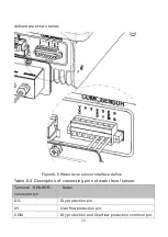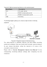
33
A
C
D
S
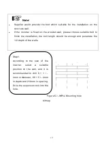
A:the Installation location of
overflow high water level sensor.
B:the Installation location of
overflow low water level sensor.
1. C:the Installation location of pump
dryed high water level sensor.
2. D:Pump outlet
,
the Installation
location of pump dryed low water
level sensor.
3. S about 1-3 m .
B
To Wa te r le v el
s en so r co nn ec to r
B1 connect To SY
B2 connect to COM
A2 connect to COM
A1 connect to DG
Figure6-8 the installation figure of Sensor A
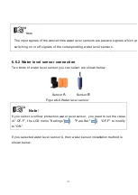
If you selected water level sensor B, then water sensor installation method is
shown below:
Figure6-9 the installation figure of Sensor B
Содержание JNP1K1L-V5
Страница 40: ...32 Figure6 7 the detail figure of Sensor A ...

