22
Figure6-1 External connection terminals of inverter
Table6-1 Description
Terminals
Description
AC IN
AC input terminals
,
including R/S/T/PE.
PV
PV array DC input terminals, including PV+/PV-.
MOTOR
Output terminal, connect with AC pump, including U/V/W.
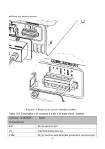
SENSOR
Water level sensor signal input terminal (optional)
COM
RS485 or GPRS communication interface (optional)
Ground terminal
6.2 Schematic Diagram of Electrical Connection
Figure 6-2 is the schematic diagram of electrical connection among PV
arrays, solar pumping inverter and three-phase AC pump. Water level sensor
and communication interface shall be connected if needed.
Содержание JNP1K1L-V5
Страница 40: ...32 Figure6 7 the detail figure of Sensor A ...


