JLG 100HX Скачать руководство пользователя страница 72

SECTION 5 - OPTIONAL EQUIPMENT

5-2

– JLG Lift –

3120889

5.7

ROTATING BEACON

An amber or red rotating beacon may be installed on the
hood or platform, and can be controlled by a two position
toggle switch mounted on the platform control console.
When the switch is placed in the ON position, the light is
activated and provides a visual warning to the machine’s
operation.

5.8

CYLINDER BELLOWS

A one piece accordion shaped rubber bellows may be
attached to the rod end of the cylinder barrel and to the
cylinder rod as close to the rod attach bushing as possi-
ble. The bellows affords protection to the cylinder rod in
either the extended or retracted position. The bellows are
installed on the lift cylinder, slave cylinder, master cylinder
and steer cylinder.

5.9

BOOM WIPERS

A one piece U-shaped neoprene strip, be attached to the
front of the base boom section, wipes the top and both
sides of the fly section. The bottom side of the fly section
is p rotected  by a straig ht neop rene strip  whic h also
attaches to the base section.

5.10 HOSTILE ENVIRONMENT PACKAGE

The hostile environment package provides additional pro-
tection against the entry of dust, dirt, sand and other abra-
sive materials into the hydraulic system, control handles
and switches, cylinders, boom wire ropes and wear pads,
and the air inlet of the engine. The package is intended for
machines that will be exposed to painting, sandblasting or
other similar hostile conditions. The hostile environment
package includes boom wipers, cylinder bellows, heavy
duty reservoir breather, an engine air cleaner and control
console cover, as required.

5.11 MOTION ALARM

A motion alarm horn provides an audible warning when
the platform controls are selected at the PLATFORM/
GROUND SELECT switch, the POWER/EMERGENCY
STOP switch is ON, and the footswitch is depressed. The
alarm warns personnel in the jobsite area to avoid the
operating machine.

5.12 DESERT ENVIRONMENT PACKAGE

The Desert Environment package is designed to provide
additional protection to the machines vital components
under extreme hot, dry and sandy conditions. This pack-
age includes the boom wipers, cylinder bellows, heavy

duty air cleaner, console cover, and air breather described
in the Hostile Environment package in this section. In
addition to these items a hydraulic oil cooler fitted with a
sand and dust filter is installed on the machine turntable.
A hydraulically driven motor serves to turn the fan which
draws air down through the sand and dust filter. The air is
then forced down through the heat exchanger cooling the
constant flow of hydraulic oil within.

5.13 110 VOLT/60HZ GENERATOR

A 110 volt generator, mounted beside the engine, is belt
driven from the output shaft of the engine. This application
provides for a 110 volt receptacle at the ground control
and also at the platform. The lead from the ground control
to the platform is routed along the boom power track thus
eliminating the use of extension cords hanging freely from
the platform.

5.14 220 VOLT RECEPTACLE

A 220 volt receptacle may be mounted on the platform
support to eliminate extension cords hanging from the
platform. The lead from the receptacle is routed along the
boom power track to the engine compartment. In the
engine compartment, a plug is installed on the lead for
attachment to an extension cord or a receptacle from a
220 volt power source. When not in use the plug is stored
in a junction box mounted on the engine compartment
frame.

5.15 SPARK ARRESTOR MUFFLER

The spark arrestor is mounted directly aft of the standard
muffler and serves to contain any sparks the engine might
emit that a standard muffler normally would not. The spark
arrestor is a vital option for machines which are operated
in areas where combustible materials are used. The spark
arrestor is available for g asoline, LP g as, and diesel
engines.

5.16 110 VOLT RECEPTACLE

A 110 volt receptacle may be mounted on the platform
control console to eliminate extension cords hanging from
the platform. The lead from the receptacle is routed along
the boom power track to the battery and ground control
c o m p artm ent at the front o f the m ac hine. A p lug  is
installed on the end of the lead for attachment to an exten-
sion cord or a receptacle from a 110 volt power source.
When not in use the excess wire and p lug  are to b e
stowed beside the battery.

Courtesy of Crane.Market 

Содержание 100HX

Страница 1: ...ralia Telephone 065 811111 Fax 065 810122 EUROPEAN OFFICE JLG INDUSTRIES EUROPE Kilmartin Place Tannochside Park Uddingston Scotland G71 5PH Telephone 01698 811005 Main Fax 01698 811055 Parts Fax 0169...

Страница 2: ...Courtesy of Crane Market...

Страница 3: ...AND OPERATION PROPER SAFETY PRACTICES ARE THE RESPONSIBILITY OF THE USER AND HIS OPER ATING PERSONNEL ALL INSTRUCTIONS IN THIS MANUAL ARE BASED ON THE USE OF THE MACHINE UNDER PROPER OPERATING CONDITI...

Страница 4: ...FOREWORD b JLG Lift 3120889 This page left blank intentionally Courtesy of Crane Market...

Страница 5: ...their function 4 The controls shall be tested each day prior to use to determine that they are in safe operating condition 5 All personnel in the platform shall at all times wear approved fall protec...

Страница 6: ...FOREWORD d JLG Lift 3120889 REVISON LOG January 1999 Original Issue Courtesy of Crane Market...

Страница 7: ...onnel Training 3 1 3 3 Operating Characteristics and Limitations 3 2 3 4 Controls and Indicators 3 6 3 5 Placards and Decals 3 19 SECTION 4 MACHINE OPERATION 4 1 Description 4 1 4 2 General 4 1 4 3 En...

Страница 8: ...10HX 3 4 3 3 Position of Least Backward Stability 100HX 10 3 5 3 4 Ground Control Station Dual Capacity Only 100HX and 110HX Prior to January 1992 3 7 3 5 Ground Control Station Single Capacity Only 1...

Страница 9: ...TENTS LIST OF TABLES TABLE NO TITLE PAGE NO 1 1 Minimum Safe Approach Distances M S A D to energized exposed or insulated power lines and parts 1 2 1 1 Lubrication Chart 2 10 7 1 Inspection and Repair...

Страница 10: ...iv JLG Lift 3120889 TABLE OF CONTENTS Continued This page left blank intentionally Courtesy of Crane Market...

Страница 11: ...on and or operation JLG Industries Inc should be consulted MODIFICATION OR ALTERATION OF AN AERIAL PLATFORM SHALL BE MADE ONLY WITH PRIOR WRITTEN PERMISSION OF THE MANUFACTURER 1 2 DRIVING TOWING Befo...

Страница 12: ...VOLTS OR LESS 1 4 PRE OPERATIONAL READ YOUR MANUAL UNDERSTAND WHAT YOU VE READ THEN BEGIN OPERATIONS ALLOW ONLY AUTHORIZED AND QUALIFIED PER SONNEL TO OPERATE MACHINE WHO HAVE DEM ONSTRATED THAT THEY...

Страница 13: ...NTAINED ACCORDING TO THE MANUFACTURERS SPECIFICATIONS AND SCHEDULE ENSURE DAILY INSPECTION AND FUNCTION CHECK IS PERFORMED PRIOR TO PLACING MACHINE INTO OPERATION NEVER DISABLE OR MODIFY THE FOOTSWITC...

Страница 14: ...AYS POSITION BOOM OVER REAR DRIVE AXLE IN LINE WITH DIRECTION OF TRAVEL REMEMBER IF BOOM IS OVER FRONT STEER AXLE DIRECTION OF STEER AND DRIVE MOVEMENT WILL BE OPPO SITE FROM NORMAL OPERATION DO NOT U...

Страница 15: ...YOU VE READ THEN BEGIN OPERATIONS PRIOR TO ENTERING AND EXITING PLATFORM AT GROUND LEVEL FULLY LOWER THE BOOM EXTEND BOOM UNTIL END OF FLY BOOM CON TACTS GROUND WITH BOOM LIFT IN THIS CONFIG URATION...

Страница 16: ...AREA OF THE MACHINE NEVER POSITION LADDERS STEPS OR SIMILAR ITEMS ON UNIT TO PROVIDE ADDITIONAL REACH FOR ANY PURPOSE WHEN RIDING IN OR WORKING FROM PLATFORM BOTH FEET MUST BE FIRMLY POSITIONED ON THE...

Страница 17: ...IRED POSITION OPERATE LEVERS WITH SLOW EVEN PRESSURE DO NOT CARRY MATERIALS ON PLATFORM RAILING UNLESS APPROVED BY JLG INDUSTRIES INC NEVER PUSH OR PULL THE MACHINE OR OTHER OBJECTS BY TELESCOPING THE...

Страница 18: ...TRACTED FOR ANY LENGTH OF TIME ALWAYS BUMP CONTROL IN OPPOSITE DIRECTION SLIGHTLY WHEN FUNCTION BEING USED REACHES END OF TRAVEL THIS APPLIES TO MACHINES IN OPERATION OR IN STOWED MODE DO NOT OPERATE...

Страница 19: ...record stamp Annual Inspection dates Check decal and notify dealer if inspection is overdue The following checklist provides a systematic inspection to assist in detecting defective damaged or improp...

Страница 20: ...and hydraulic lines for damage leakage and security NOTE JLG recommends replacing the hydraulic filter ele ment after the first 50 hours of operation and then every 300 hours thereafter unless system...

Страница 21: ...SECTION 2 PREPARATION AND INSPECTION 3120889 JLG Lift 2 3 Figure 2 1 Machine Nomenclature Courtesy of Crane Market...

Страница 22: ...or inspect the machine before operation even if the machine has already been put into service under another operator This Daily Walk Around Inspection is the preferred method of inspection See Figure...

Страница 23: ...SECTION 2 PREPARATION AND INSPECTION 3120889 JLG Lift 2 5 Figure 2 2 Daily Walk Around Inspection Diagram Courtesy of Crane Market...

Страница 24: ...ge 7 Power Track No loose damaged or missing parts no visible damage 8 Drive Motor and Brake Right Rear No visible dam age no evidence of leakage 9 Drive Hub Right Rear No visible damage no evi dence...

Страница 25: ...n 31 Frame No visible damage no loose or missing hardware top and underside 32 Drive Hub Left Rear No visible damage no evi dence of leakage 33 Wheel Tire Assembly Left Rear Properly secured no loose...

Страница 26: ...rom the ground it may be nec essary to feather the lift control to maintain drive wheel elevation e With the aid of an assistant position EXTEND ABLE AXLE STEER switch located on platform control cons...

Страница 27: ...SECTION 2 PREPARATION AND INSPECTION 3120889 JLG Lift 2 9 Figure 2 5 Lubrication Point Location Courtesy of Crane Market...

Страница 28: ...ingEach MPG PressureGun 150 14 Drive Hubs FillPlug EPGL SAE90 150 1200 Checkevery150hrs Changeevery1200hrs 15 Swing Bearing Gear N A MPG Brush 150 16 Swing Bearing 1GreaseFitting MPG PressureGun 150 1...

Страница 29: ...ed marking band on the inner mid section is exposed from the base section The red light should illuminate at this point c Continue extending the boom until the white marking band on the inner mid sect...

Страница 30: ...illuminate shut down machine and contact a qualified service technician before continuing operation 14 Footswitch FOOTSWITCH MUST BE ADJUSTED SO THAT FUNCTIONS WILL OPERATE WHEN PEDAL IS APPROXIMATELY...

Страница 31: ...per service per sonnel can be notified The Service and Maintenance manual provides specific torque values and periodic maintenance procedures with a listing of individual com ponents Utilizing this To...

Страница 32: ...4623 0 3604 0 2700 0 1969 0 1331 0 0925 0 0508 0 0808 0 0445 0 0356 0 0232 0 0153 0 0374 0 0258 0 0168 2 7254 2 1742 1 6840 1 2929 0 9474 0 6502 0 5156 0 4061 0 3015 0 2230 0 1473 3 1750 2 8575 2 5400...

Страница 33: ...rgency controls and safety systems 2 Knowledge and understanding of this manual and of the control markings instructions and warnings on the machine itself 3 Knowledge and understanding of all safety...

Страница 34: ...ove horizontal and or the extension of the boom beyond the retracted position with or without any load in the platform is based on the following criteria 1 Machine is positioned on a smooth firm and l...

Страница 35: ...SECTION 3 USER RESPONSIBILITIES AND MACHINE CONTROL 3120889 JLG Lift 3 3 Figure 3 1 Position of Least Forward Stability Courtesy of Crane Market...

Страница 36: ...SECTION 3 USER RESPONSIBILITIES AND MACHINE CONTROL 3 4 JLG Lift 3120889 Figure 3 2 Position of Least Backward Stability 100HX and 110HX Courtesy of Crane Market...

Страница 37: ...SECTION 3 USER RESPONSIBILITIES AND MACHINE CONTROL 3120889 JLG Lift 3 5 Figure 3 3 Position of Least Backward Stability 100HX 10 Courtesy of Crane Market...

Страница 38: ...HES CONTROLLING PLATFORM MOVEMENT DO NOT RETURN TO THE OFF POSITION WHEN RELEASED 3 Ignition Switch The machine is equipped with an on off ignition switch and a separate start push button switch on th...

Страница 39: ...SECTION 3 USER RESPONSIBILITIES AND MACHINE CONTROL 3120889 JLG Lift 3 7 Figure 3 4 Ground Control Station Dual Capacity Only 100HX and 110HX Prior to January 1992 Courtesy of Crane Market...

Страница 40: ...SECTION 3 USER RESPONSIBILITIES AND MACHINE CONTROL 3 8 JLG Lift 3120889 Figure 3 5 Ground Control Station Single Capacity Only 100HX 10 Prior to January 1992 Courtesy of Crane Market...

Страница 41: ...SECTION 3 USER RESPONSIBILITIES AND MACHINE CONTROL 3120889 JLG Lift 3 9 Figure 3 6 Ground Control Station 100HX and 110HX January 1992 to Present Courtesy of Crane Market...

Страница 42: ...SECTION 3 USER RESPONSIBILITIES AND MACHINE CONTROL 3 10 JLG Lift 3120889 Figure 3 7 Ground Control Station 100HX 10 January 1992 to Present Courtesy of Crane Market...

Страница 43: ...ons will operate at a slower than normal rate due to the lower amount of hydraulic flow provided 10 Glow Plug Switch Diesel Engine Only The push button switch relays power to the glow plugs used to wa...

Страница 44: ...s used in con juction with the Load Management Test Switch for checking the Load Management System The switch is used to reset the system during the checking pro cedure Platform Station NOTE For engin...

Страница 45: ...SECTION 3 USER RESPONSIBILITIES AND MACHINE CONTROL 3120889 JLG Lift 3 13 Figure 3 8 Platform Station 100HX and 110HX Prior to Sept 1991 Courtesy of Crane Market...

Страница 46: ...SECTION 3 USER RESPONSIBILITIES AND MACHINE CONTROL 3 14 JLG Lift 3120889 Figure 3 9 Platform Station 100HX 10 Prior to Sept 1991 Courtesy of Crane Market...

Страница 47: ...SECTION 3 USER RESPONSIBILITIES AND MACHINE CONTROL 3120889 JLG Lift 3 15 Figure 3 10 Platform Station 100HX and 110HX Sept 1991 to Present Courtesy of Crane Market...

Страница 48: ...SECTION 3 USER RESPONSIBILITIES AND MACHINE CONTROL 3 16 JLG Lift 3120889 Figure 3 11 Platform Station 100HX 10 Sept 1991 to Present Courtesy of Crane Market...

Страница 49: ...ues to operate at a lower speed DO NOT OPERATE MACHINE IF HIGH ENGINE SPEED HIGH WHEEL MOTOR SPEED OR HIGH PUMP VOLUME OPERATE WHEN BOOM IS ABOVE HORIZONTAL 10 High Engine The two position HIGH ENGINE...

Страница 50: ...Set Indicator If equipped The green AXLES SET indicator lights to inform the operator that the axles are set and locked pinned in position 21 Lights Switch If equipped The LIGHTS switch allows the op...

Страница 51: ...llegible Decals are made of Lexan Pressure Sensitive Adhesive with a protective film on the front Remove the damaged decal and thoroughly clean the surface before installing a new decal Simply peel of...

Страница 52: ...SECTION 3 USER RESPONSIBILITIES AND MACHINE CONTROL 3 20 JLG Lift 3120889 Figure 3 12 Caution Danger Warning Decal Location Sheet 1 of 2 Courtesy of Crane Market...

Страница 53: ...SECTION 3 USER RESPONSIBILITIES AND MACHINE CONTROL 3120889 JLG Lift 3 21 Figure 3 13 Caution Danger Warning Decal Location Sheet 2 of 2 Courtesy of Crane Market...

Страница 54: ...DBOOK TO ENSURE SAFE OPERATION OF THE MACHINE CAUTION 1690696 1690697 B MAX 12 5 m s MAX FORCE 400N 2 PERSONS 70KG SWL 230KG THIS MACHINE MUST ONLY BE OPERATED BY TRAINED PERSONNEL REFERENCES SHOULD B...

Страница 55: ...SECTION 3 USER RESPONSIBILITIES AND MACHINE CONTROL 3120889 JLG Lift 3 23 Figure 3 14 Common Symbols Sheet 1 Courtesy of Crane Market...

Страница 56: ...SECTION 3 USER RESPONSIBILITIES AND MACHINE CONTROL 3 24 JLG Lift 3120889 Figure 3 15 Common Symbols Sheet 2 Courtesy of Crane Market...

Страница 57: ...SECTION 3 USER RESPONSIBILITIES AND MACHINE CONTROL 3120889 JLG Lift 3 25 Figure 3 16 Common Symbols Sheet 3 Courtesy of Crane Market...

Страница 58: ...SECTION 3 USER RESPONSIBILITIES AND MACHINE CONTROL 3 26 JLG Lift 3120889 Figure 3 17 Common Symbols Sheet 4 Courtesy of Crane Market...

Страница 59: ...t of service until all discrepancies are corrected The JLG Lift is not intended to be used to lift material other than supplies which personnel in the platform require to do their job Supplies or tool...

Страница 60: ...p position before starter will operate If starter operates with footswitch in the depressed position DO NOT OPERATE THE MACHINE Shutdown Procedure IF AN ENGINE MALFUNCTION NECESSITATES UNSCHEDULED SHU...

Страница 61: ...ate the following switches a Position HIGH ENGINE switch to HIGH b Position WHEEL MOTOR SPEED switch to HIGH c Position PUMP VOLUME switch to HIGH 5 Prior to stopping the machine position switches as...

Страница 62: ...EVEL control switch to DOWN and hold until platform is level Platform Rotation 1 Depress footswitch to rotate platform to the left PLATFORM ROTATE control is positioned to the LEFT and held until desi...

Страница 63: ...g the steer control for removal of lock pins d Position the LIFT control to DOWN and hold until the steer wheels rise from the ground it may be necessary to feather the LIFT control to maintain wheel...

Страница 64: ...b If retracting the drive axles remove the axle lock pins If retracting the steer axles remove the tie rod lock pins steer cylinder pin and axle lock pins NOTE It may be necessary to elevate the wheel...

Страница 65: ...SECTION 4 MACHINE OPERATION 3120889 JLG Lift 4 7 Figure 4 3 Lifting Chart 100HX and 110HX Courtesy of Crane Market...

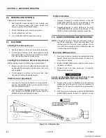
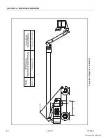
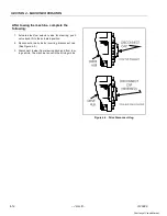
Страница 66: ...SECTION 4 MACHINE OPERATION 4 8 JLG Lift 3120889 Figure 4 4 Lifting Chart 100HX 10 Courtesy of Crane Market...

Страница 67: ...FROM FOOTSWITCH OR USE EMERGENCY STOP TO STOP THE MACHINE Swinging the Boom ASSURE THAT TURNTABLE LOCK IS DISENGAGED BEFORE STARTING ANY SWING OPERATION 1 Depress footswitch to swing boom position SWI...

Страница 68: ...MAGE THE MACHINE A push pull type selector valve located adjacent to the steer cylinder assembly and linkage regulates oil flow in the steer circuit for steering and towing applications When steering...

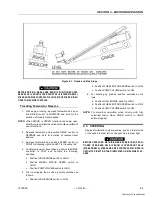
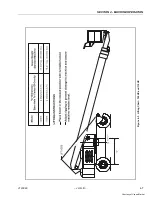
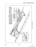
Страница 69: ...SECTION 4 MACHINE OPERATION 3120889 JLG Lift 4 11 Figure 4 5 Machine Tie Down Courtesy of Crane Market...

Страница 70: ...steer tow selector valve for steering push valve knob IN to the actuated position 2 Reconnect drive hubs by inverting disconnect cap See Figure 4 5 3 Disconnect towbar from steering hitch and from tow...

Страница 71: ...s engine begins to stumble place the switch to LP position allowing LP gas to flow to the fuel regulator Changing From LP Gas to Gasoline 1 With engine operating on LP under a no load condi tion posit...

Страница 72: ...oom wipers cylinder bellows heavy duty air cleaner console cover and air breather described in the Hostile Environment package in this section In addition to these items a hydraulic oil cooler fitted...

Страница 73: ...side of the turntable The controls on this panel provide the means for overriding the platform controls and for controlling the platform level boom and swing functions from the ground Place the SELECT...

Страница 74: ...ved to a secure location Only then should an attempt be made to free the platform using any necessary equipment and per sonnel Do not operate controls to cause one or more wheels to leave the ground R...

Страница 75: ...SECTION 7 INSPECTION AND REPAIR LOG 3120889 JLG Lift 7 1 SECTION 7 INSPECTION AND REPAIR LOG Table 7 1 Inspection and Repair Log Date Comments Courtesy of Crane Market...

Страница 76: ...SECTION 7 INSPECTION AND REPAIR LOG 7 2 JLG Lift 3120889 Table 7 1 Inspection and Repair Log Date Comments Courtesy of Crane Market...

Страница 77: ...o the current ownership of JLG Products Please return completed form to the JLG Product Safety Reliability Department via facsimile 717 485 6573 or mail to address as specified on the back of this for...

Страница 78: ...Courtesy of Crane Market...

Страница 79: ...Courtesy of Crane Market...

Страница 80: ...Suite 71 13092 310 Campinas SP Brazil Phone 55 19 3295 0407 Fax 55 19 3295 1025 JLG Europe B V Jupiterstraat 234 2132 HJ Foofddorp The Netherlands Phone 31 23 565 5665 Fax 31 23 557 2493 JLG Industrie...

Отзывы: