8
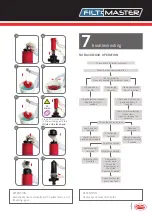
Continuous
backwash
Disconnect the control
micropipes from
the valves
Check inlet / outlet pressure
Check pressure differential gauge
and replace if needed
Check controller described above
Command
transfer
Check
controller
No command
transfer
Check the
solenoid
No command
transfer
Check the
hydraulic relay
No command
transfer
Command transfer
Replace the solenoid
if needed
Command transfer
Replace the hydraulic
relay if needed
Command
transfer
Replace control
panel
No command
transfer
Disconnect the
drain manifold
Locate the
nonfunctioning valve
Remove any obstruction
Repair the valve if needed
Nonstop backwash
cycle
Force backwash
manually
Contact your
local distributor
ATTENTION
Contact your local distributor.
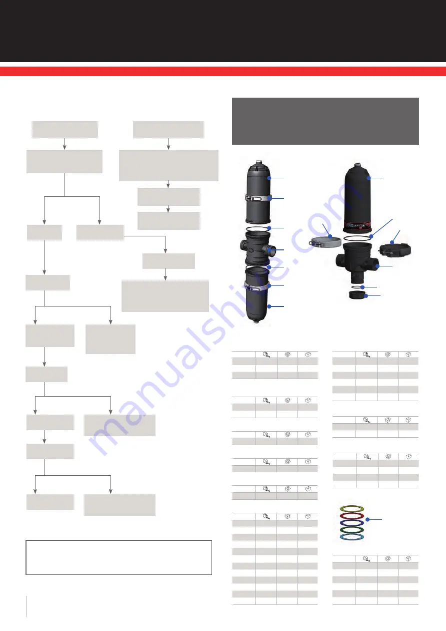
Spare parts
and accessories
8
10
Operation and maintenance manual
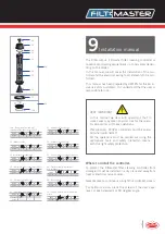
1.- Filter cover
Code
97824
2” Std.
1
A-2
97345
2”
1
A-11
97346
3” / 2” L
1
A-4
1.- Transparent filter cover
(only for demonstration purpose)
Code
97347
2”
1
A-2
97348
3” / 2” L
1
A-4
2.- AISI 304 stainless steel clamp
Code
97350
2”- 3”
1
A-1
4.- Filter body o-ring
Code
97351
2”- 3”
10
A-10
5.- Filter body (3 ways)
Code
97770
2”- BBB
1
A-11
97772
2”- VBV
1
A-11
97771
2”- VVB
1
A-11
97773
2”- NNN
1
A-11
97775
2”- VNV
1
A-11
97774
2”- VVN
1
A-11
97777
3”- BBB
1
A-8
97779
3”- VBV
1
A-8
97778
3”- VVB
1
A-8
97780
3”- NNN
1
A-8
97782
3”- VNV
1
A-8
97781
3”- VVN
1
A-8
6.- Filter body (2 ways)
Code
97785
3”- BB
1
A-9
97784
3”- NN
1
A-9
97786
3”- VV
1
A-9
97788
4”- BB
1
A-8
97787
4”- NN
1
A-8
97789
4”- VV
1
A-9
7.- O-ring for cap
Code
97802
2”
1
4114
97803
3”
1
4114
10.- Discs kit (500 units)
Code
98813
20M
1
A-11
98495
25M
1
A-2
98814
50M
1
A-2
98815
100M
1
A-11
98816
130M
1
A-11
98817
200M
1
A-11
CONTINUOUS OR NON-STOP BACKWASHING
1
1
5
7
8
2
3
4
2
4
6
4
2
1
3.- PAFV clamp
(polyamide reinforced with fiberglass)
Code
97759
2”- 3”
1
A-2
8.- Female threaded cap
Code
51512
2” BSP
25
A-1
51535
3” BSP
15
A-2
51513
2” NPT
25
A-1
51536
3” NPT
15
A-2

