background image

4

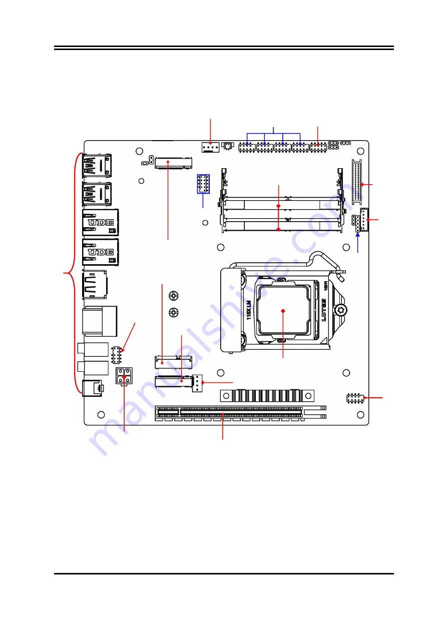
For MI02-40/42:

*Rear IO

Connector

(Refer to Page-2)

LGA 1200

CPU Socket

M.2 M-Key Slot

(M2M)

M.2 E-Key Slot

(M2E)

Front Panel

Header

PCI Express x16 Slot

(PCIE1)

M.2 B-key Slot

(*M2B)

SYSFAN1

Connector

Serial Port Headers

(COM1/2/3/4)

GPIO Port

Header

2*DDR4

SODIMM Slots

LVDS Header

INVERTER

SMBUS

Header

USB 2.0

Header

CPUFAN

Connector

Front Panel

Audio Header

ATX 12V

Power Connector

DCIN2

Содержание MI02 Series

Страница 1: ...lease date October 26 2021 Trademark Specifications and Information contained in this documentation are furnished for information use only and are subject to change at any time without notice and should not be construed as a commitment by manufacturer ...

Страница 2: ...ARDWARE INSTALLATION 2 1 JUMPER SETTING 8 2 2 CONNECTORS AND HEADERS 10 2 2 1 REAR I O BACK PANEL CONNECTORS 10 2 2 2 MOTHERBOARD INTERNAL CONNECTORS 11 2 2 3 HEADER PIN DEFINITION 14 CHAPTER 3 INTRODUCING BIOS 3 1 ENTERNING SETUP 18 3 2 BIOS MENU SCREEN 19 3 3 FUNCTION KEYS 19 3 4 GETTING HELP 20 3 5 MENU BARS 20 3 6 MAIN MENU 20 3 7 ADVANCED MENU 21 3 8 CHIPSET MENU 32 3 9 BOOT MENU 34 3 10 SECU...

Страница 3: ...drops attached on PCB or the surface of the components can bring about phenomena as minor as computer instability resulted from corrosion and oxidation from components and PCB or as major as short circuit that can burn the components Suggest starting the computer until the temperature goes up The increasing temperature of the capacitor may decrease the life of computer Using the close case may dec...

Страница 4: ...ANUFACTURER PROVIDES THIS MANUAL AS IS WITHOUT WARRANTY OF ANY KIND AND WILL NOT BE LIABLE FOR ANY INDIRECT SPECIAL INCIDENTAL OR CONSEQUENTIAL DAMAGES INCLUDING DAMAGES FOR LOSS OF PROFIT LOSS OF BUSINESS LOSS OF USE OF DATA INTERRUPTION OF BUSINESS AND THE LIKE PRODUCTS AND CORPORATE NAMES APPEARING IN THIS MANUAL MAY OR MAY NOT BE REGISTERED TRADEMARKS OR COPYRIGHTS OF THEIR RESPECTIVE COMPANIE...

Страница 5: ...230 PCIex1 USB2 0 slot M2B 1 M 2 B key type 3042 3052 USB3 0 PCIex1 slot co function with SIM card slot SIMCARD1 1 Nano SIM card slot Backside co function with M2B Note For M2E M2B slot maximum current limit is 2A while using 3 3V Storage SATA1 1 SATAIII 6Gb s port Optional M2M 1 M 2 M key slot type 2280 SATA PCIex4 slot supports NVMe Note M2M slot maximum current limit is 2A while using 3 3V PCIe...

Страница 6: ...12 MI02 20 22 MI02 30 32 MI02 40 42 Chipset Q470E W480E H470 H420E LAN Chip I219LM I225LM I219LM I225LM I219V I225LM I219V I225LM Rear IO USB 3 2 4 USB3 2 Gen2 4 USB3 2 Gen2 4 USB3 2 Gen2 4 USB3 2 Gen1 Intenal USB 3 1 Gen1 Header Yes Yes Yes N A Intenal USB 2 0 Header 2 9 pin USB2 0 2 9 pin USB2 0 2 9 pin USB2 0 1 9 pin USB2 0 SATAIII SATA Power out Yes Yes Yes N A Multi Display Support Triple Dis...

Страница 7: ...ey Slot M2M M 2 E Key Slot M2E Front Panel Header PCI Express x16 Slot PCIE1 M 2 B key Slot M2B SATA Power out Connector SYSFAN1 Connector Serial Port Headers COM1 2 3 4 GPIO Port Header 2 DDR4 SODIMM Slots LVDS Header INVERTER SMBUS Header USB 2 0 Headers USB 3 2 Gen 1 Header CPUFAN Connector Front Panel Audio Header ATX 12V Power Connector DCIN2 ...

Страница 8: ... M 2 E Key Slot M2E Front Panel Header PCI Express x16 Slot PCIE1 M 2 B key Slot M2B SYSFAN1 Connector Serial Port Headers COM1 2 3 4 GPIO Port Header 2 DDR4 SODIMM Slots LVDS Header INVERTER SMBUS Header USB 2 0 Header CPUFAN Connector Front Panel Audio Header ATX 12V Power Connector DCIN2 ...

Страница 9: ...erboard Internal Diagram Back Note SIM card slot only functions when compatible Nano SIM card installed compatible 3G 4G 5G card installed in M2B slot Intel Chipset EDP Connector Nano SIM Card Holder SIMCARD1 ...

Страница 10: ...e Description Pitch JAT_ATX ATX AT Mode Select 3 pin Block 2 0mm JBAT Clear CMOS RAM Settings 3 pin Block 2 0mm JP2 LVDS INVERTER Backlight VCC Select 3 pin Block 2 0mm JP3 LVDS PANEL VCC Select 3 pin Block 2 0mm COPEN Case Open Message Display Detect 2 pin Block 2 0mm JP1 ME Features Select 2 pin Block 2 0mm JAT_ATX JBAT JP3 COPEN JP1 JP2 ...

Страница 11: ... for MI02 10 20 30 MI02 12 22 32 series only Headers Header Name Description Pitch JW_FP Front Panel Header PWR LED HD LED Power Button Reset 9 pin Block 2 54mm FP_USB1 USB 3 2 Gen 1 Port Header 19 pin Block 2 0mm FP_USB2 USB 2 0 Port Header 9 pin Block 2 0mm FP_USB3 USB 2 0 Port Header 9 pin Block 2 0mm COM1 2 RS232 422 485 Serial Port Header 9 pin Block 2 0mm COM3 4 RS232 Serial Port Header 9 pi...

Страница 12: ...T Mode ATX Mode Select ATX Mode Selected Press power button to power on after power input ready AT Mode Selected Directly power on as power input ready JBAT 3 pin Clear CMOS RAM Settings 2 3 Closed Clear CMOS 1 2 Open Normal 1 3 1 3 JBAT Clear CMOS Settings JBAT JAT_ATX ...

Страница 13: ... Open Message Display Function Pin1 COPEN Case Open Detection CASE OPEN GND Pin 1 2 Short When Case open function pin short to GND the Case open function was detected When Used needs to enter BIOS and enable Case Open Detect function In this case if your case is removed next time when you restart your computer a message will be displayed on screen to inform you of this JP3 JP2 COPEN ...

Страница 14: ...ication RJ 45 LAN Port This connector is standard RJ 45 LAN jack for Network connection LAN1 Intel i219 LM i219 V PHY LAN port supports up to 1 0 Gbps transfer rate LAN2 from Intel i225 LM supports up to 2 5Gbps transfer rate Display Port For user to the system to corresponding display device with compatible DP cable HDMI 1 4 Port To connect display device that support HDMI specification Line out ...

Страница 15: ...onnector that usually comes with ATX Power Supply that supports extra 12V voltage to maintain system power consumption Without this connector might cause system unstable because the power supply can not provide sufficient current for system Pin No Definition 1 GND 2 GND 3 12V 4 12V Pin1 4 2 3 2 SATA1 7 pin SATAIII Port connector SATA1 is only optional for MI02 10 20 30 MI02 12 22 32 series This is...

Страница 16: ... compatible SATA Power out connector is inserted into corresponding Pin 1 of PWROUT connector to avoid possible damage to the board and hard disk driver 4 SYSFAN1 4 pin System FAN Connector Fan Speed GND Pin1 12V Fan Power Control Note Maximum current limit is 1 5A while using 12V working voltage 5 CPUFAN 4 pin CPU FAN Connector 12V Fan Power GND Fan Speed Control Pin1 Note Maximum current limit i...

Страница 17: ...LANE1P Pin 30 GND Pin 11 GND Pin 31 GND Pin 12 EDP_LANE0N Pin 32 EDP_BKLT_EN Pin 13 EDP_LANE0P Pin 33 EDP _BKLT_CTL Pin 14 GND Pin 34 NC Pin 15 EDP_AUXP Pin 35 NC Pin 16 EDP_AUXN Pin 36 LCD_BKLT_PWR VCC Pin 17 GND Pin 37 LCD_BKLT_PWR VCC Pin 18 LCD_VCC Pin 38 LCD_BKLT_PWR VCC Pin 19 LCD_VCC Pin 39 LCD_BKLT_PWR VCC Pin 20 LCD_VCC Pin 40 NC Note The board co lays LVDS header and EDP connector i e on...

Страница 18: ...D GND1 SSRX1 VBUS_5V SSTX2 SSTX2 GND3 VBUS_5V 11 10 SSRX2 SSRX2 SSRX1 SSTX1 SSTX1 D2 D Note Maximum current limit is 1 5A in total while using 5V working voltage 3 FP_USB2 FP_USB3 9 pin USB 2 0 Port Headers FP_USB3 is only optional for MI02 10 20 30 MI02 12 22 32 series DATA NC GND DATA GND VCC5V DATA Pin1 VCC5V DATA 2 Note Maximum current limit is 1 5A in total while using 5V working voltage JW_F...

Страница 19: ...RI NC NC Notice COM1 2 header can function as RS232 422 485 port header In normal settings COM1 2 functions as RS232 header With compatible COM cable COM1 2 can function as RS422 or RS 485 header User also needs to go to BIOS to set Transmission Mode Select for COM1 or COM2 at first before using specialized cable to connect different pins of this port 5 GPIO 10 pin GPIO Port Header VCC Pin1 2 GPIO...

Страница 20: ... In Header This header connects to Front Panel Line out MIC In connector with cable GND MIC_JD SENSE LINE_OUT_R Pin 1 MIC2_L AUDIO_JD 2 MIC2_R LINE OUT_L LINE_OUT_JD 8 INVERTER1 6 pin LVDS Inverter Pin No Definition 1 BKLT_PWR1 2 BKLT_PWR2 3 BKLT_EN 4 BKLT_PWM 5 BKLT_GND1 6 BKLT_GND2 Pin1 Note Maximum current limit is 2A in total while using 12V working voltage SMBUS1 FP_AUDIO INVERTER1 ...

Страница 21: ...B_DATAN1 Pin 7 Pin 8 LVDSB_DATAP1 LVDSB_DATAN0 Pin 9 Pin 10 LVDSB_DATAP0 LVDS_DDC_SDA Pin 11 Pin 12 LVDS_DDC_SCL GND Pin 13 Pin 14 GND GND Pin 15 Pin 16 GND LVDSA_DATAP3 Pin 17 Pin 18 LVDSA_DATAN3 LVDSA_CLKP Pin 19 Pin 20 LVDSA_CLKN LVDSA_DATAP2 Pin 21 Pin 22 LVDSA_DATAN2 LVDSA_DATAP1 Pin 23 Pin 24 LVDSA_DATAN1 LVDSA_DATAP0 Pin 25 Pin 26 LVDSA_DATAN0 LCD_VCC Pin 27 Pin 28 LCD_VCC LCD_VCC Pin 29 Pi...

Страница 22: ...dware device and configures the parameters of the hardware synchronization Only when these tasks are completed done it gives up control of the computer to operating system OS Since the BIOS is the only channel for hardware and software to communicate it is the key factor for system stability and in ensuring that your system performance as its best 3 1 Entering Setup Power on the computer and by pr...

Страница 23: ... of this chapter but let us first see a short description of the function keys you may use here Press right left to select screen Press up down to choose in the main menu the option you want to confirm or to modify Press Enter to select Press keys when you want to modify the BIOS parameters for the active option F1 General help F2 Previous values F3 Optimized defaults F4 Save Exit Press Esc to exi...

Страница 24: ...Main To change system basic configuration Advanced To change system advanced configuration Chipset To change chipset configuration Security Password settings Boot To change boot settings Save Exit Save setting loading and exit options User can press the right or left arrow key on the keyboard to switch from menu bar The selected one is highlighted 3 6 Main Menu Main menu screen includes some basic...

Страница 25: ...s are only optional for MI02 series with Q470E W480E and H470 chipset For Advanced Menu these main items include Differences Q470E W480E H470 H420E Connectivity Configuration yes yes yes N A AMT Configuration yes yes yes N A LAN Chip I219LM I225LM I219LM I225LM I219V I225LM I219V I225LM There are also some minor differences in sub items and setting parameters we will mark out these differences dep...

Страница 26: ...ize the additional hardware capabilities provided by Vanderpool Technology The optional settings Disabled Enabled Intel SpeedStep tm This item allows more than two frequency ranges to be supported The optional settings Disabled Enabled C states Use this item to enable or disable CPU Power Management When set as Enabled it allows CPU to go to C states when it s not 100 utilized The optional setting...

Страница 27: ...it will be lost Firmware Update Configuration Use this item to configure management engine Technology Parameter press Enter to make settings for ME FW Image Re Flash ME FW Image Re Flash Use this item to enable or disable ME FW Image Re Flash function The optional settings Disabled Enabled AMT Configuration Note AMT Configuration is optional for MI02 series with Q470E W480E H470 chipset Use this i...

Страница 28: ...for in the following sub items Secure Erase Mode Use this item to change Secure Erase module behavior The optional settings are Simulated Real Simulated Performs SE flow without erasing SSD Real Erase SSD Force Secure Erase This item is for user to force Secure Erase on next boot The optional settings are Disabled Enabled OEM Flags Settings Use this item to configure OEM flags Press Enter to make ...

Страница 29: ...order to change state of Security device The optional settings are None TPM Clear ACPI Settings Press Enter to make settings for the following sub items ACPI Settings ACPI Sleep State Use this item to select the highest ACPI sleep state the system will enter when the SUSPEND button is pressed The optional settings are Suspend Disabled S3 Suspend to RAM Wake up Function Settings Press Enter to make...

Страница 30: ...s in the following items Change Settings Use this item to select an optimal setting for super IO device The optional settings IO 3F8h IRQ 4 IO 3F8h IRQ 3 4 5 7 10 11 IO 2F8h IRQ 3 4 5 7 10 11 IO 3E8h IRQ 3 4 5 7 10 11 IO 2E8h IRQ 3 4 5 7 10 11 Transmission Mode Select The optional settings are RS422 RS232 RS485 Mode Speed Select The optional settings are RS232 RS422 RS485 250kbps RS232 1Mbps RS422...

Страница 31: ...led When set as Enabled user can make further settings in the following items Change Settings Use this item to select an optimal setting for super IO device The optional settings IO 2E8h IRQ 10 IO 3F8h IRQ 3 4 5 7 10 11 IO 2F8h IRQ 3 4 5 7 10 11 IO 3E8h IRQ 3 4 5 7 10 11 IO 2E8h IRQ 3 4 5 7 10 11 IO 3E0h IRQ 3 4 5 7 10 11 IO 2E0h IRQ 3 4 5 7 10 11 WatchDog Reset Timer Use this item to enable or di...

Страница 32: ...ill run at idle speed when below this pre set duty Serial Port Console Redirection COM1 Console Redirection The optional settings are Disabled Enabled When set as Enabled the following sub items shall appear Console Redirection Settings The settings specify how the host computer and the remote computer which the user is using will exchange data Both computers should have the same or compatible set...

Страница 33: ... will be sent This is to capture Terminal data The optional settings are Disabled Enabled Resolution 100x31 Use this item to enable or disable extended terminal resolution The optional settings Disabled Enabled Putty KeyPad Use this item to select FunctionKey and KeyPad on Putty The optional settings are VT100 Linux XTERMR6 SCO ESCN VT400 Serial Port for Out of Band Management Windows Emergency Ma...

Страница 34: ...is item to enable or disable USB mass storage driver support The optional settings are Disabled Enabled USB hardware delays and time outs USB Transfer time out Use this item to set the time out value for control bulk and interrupt transfers The optional settings are 1 sec 5 sec 10 sec 20 sec Device reset time out Use this item to set USB mass storage device start unit command time out The optional...

Страница 35: ...en set as Enabled the following sub items shall appear Option ROM execution Network This option controls the execution of network OpROM The optional settings are Do not launch UEFI Legacy Storage This option controls the execution of UEFI and Legacy Storage OpROM The optional settings are Do not launch UEFI Legacy Other PCI devices This item is for system to determine OpROM execution policy for de...

Страница 36: ...ettings are Auto Disable Enable Aperture Size Use this item to select the Aperture Size Above 4GB MMIO BIOS assignment is automatically enabled when selecting 2048MB aperture To use this feature please disable CSM Support The optional settings are 128MB 256MB 512MB 1024MB 2048MB DVMT Pre allocated Use this item to select DVMT 5 0 Pre Allocated Fixed Graphics Memory size used by the Internal Graphi...

Страница 37: ...8 X8 The optional settings are X16 X8 X8 When set as X8 X8 users can make more settings in PCIE1 Slot Bifurcation PCIE1 Slot Enable Root Port Use this item to enable or disable the root port Root port will always enable if set x8 Bifurcation The optional settings are Disabled Enabled Auto Max Link Speed Use this item to configure PEG 0 1 0 Max Speed The optional settings are Auto Gen1 Gen2 Gen3 PC...

Страница 38: ...rator Password If there is no password present on system please press Enter to create new administrator password If password is present on system please press Enter to verify old password then to clear change password Press again to confirm the new administrator password User Password If there is no password present on system please press Enter to create new user password If password is present on...

Страница 39: ... to force system into User Mode Install factory default Secure Boot Key databases Reset to Setup Mode Use this item to delete all Secure Boot key databases from NVRAM Export Secure Boot variables Use this item to copy NVRAM content of Secure Boot variables to files in a root folder on a file system device Enroll Efi Image This item allows the image to run in Secure Boot Mode Enroll SHA256 Hash cer...

Страница 40: ... Timeout Use this item to set number of seconds to wait for setup activation key Bootup Numlock State Use this item to select keyboard numlock state The optional settings are On Off Quiet Boot Use this item to enable or disable quiet boot option The optional settings are Disabled Enabled Boot Option Priorities ...

Страница 41: ... item allows user to reset the system without saving any changes Default Options Restore Defaults Use this item to restore load default values for all the setup options Save as User Defaults Use this item to save the changes done so far as user defaults Restore User Defaults Use this item to restore the user defaults to all the setup options Boot Override ...

Отзывы: