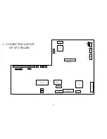

4
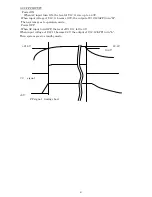
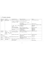
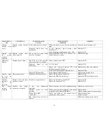
Section 2
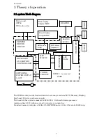
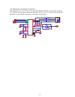
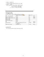
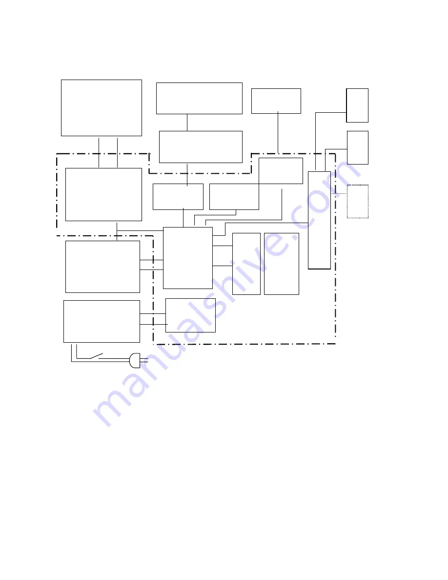
3 Theory of operation
3.1 system block diagram
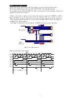
SCOM3
is reserved
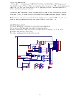
The ECR circuitry can be broken down into six major sections: MPU, Memory, Display,
Key board, Printer, and power supply.
The heart of this system consists of a M16C/80,
Sixteen bit microprocessor
implementing L.S.I, high speed, and low power consumption.
Standard memory includes a 512k x 8 bit EPROM and a 512k x 8 bit static RAM chip.
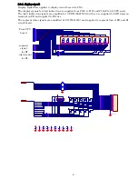
Printer unit
GTP58
With auto cutter
Front display
9 digit(LED)
SCO
M
1
SCO
M
2
Rear display
9 digits(LED)
MPU
M16C/80
E-PR
OM’(4
M
)
4M
RAM
232C DRIVER
KEY BOARD
9 X 8 MATRIX
CONTROL LOCK
PRINTER
DRIVER
CIRCUIT
DRAWER
DRAWER
DRIVER
POWER
CIRCUIT
LED driver
(digit)
SCO
M
3
SWITCHING
POWER SUPPLY
(+24V)
MAIN
LED driver
(segment)