Setup and Survey
Receiver Setup
External Antenna Setup
73
www.javad.com
2. Record the antenna height, point name, and start time in the field notes.
4.1.3. External Antenna Setup
The TRIUMPH-1 receiver can also be used with an external antenna. Follow the steps below to
connect an external antenna to TRIUMPH-1 and measure its offset.
1. Attach the antenna to a tripod or bipod and center it over the point at which data will be
collected.
2. Measure the antenna height, as described in “Measure Antenna Height” on page 72.
3. Record the antenna height, point name, and start time in the field notes.
4. Attach the flexible RF cable from the external antenna to the antenna connector on the
bottom panel of the receiver.
The TRIUMPH-1 antenna default is set to Auto, allowing the receiver to detect automatically the
available antenna (whether internal or external). If you have changed this setting, or the receiver does
not detect the external antenna, use the procedure described on page 59 to set the External Antenna
detection option.
4.1.4. External UHF Modem Setup
1. Connect the external modem to the receiver’s serial port B using serial cable.
2. Attach power cable to modem to power it.
55
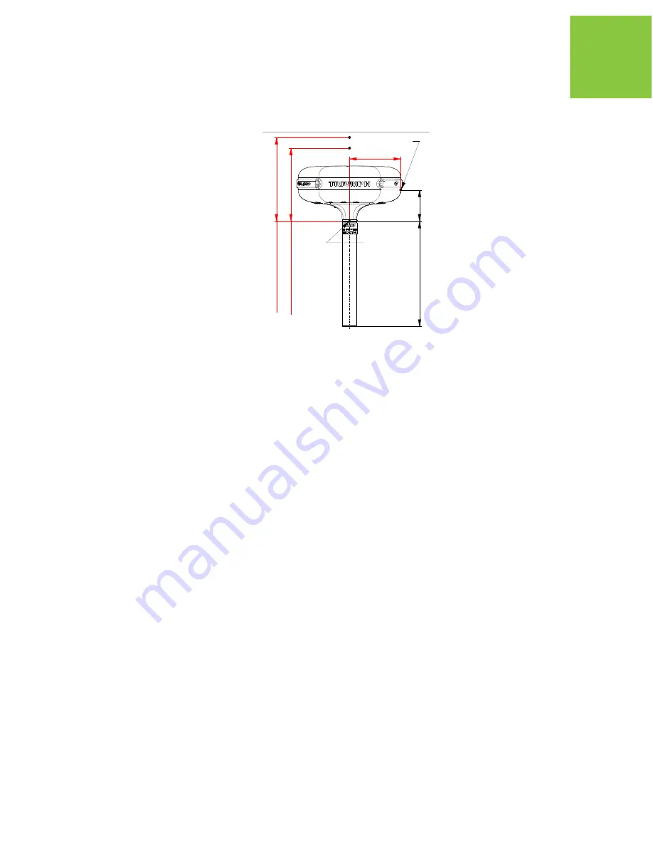
88.75
182*
L2 Up Offset: 105.7
L1 Up Offset: 111.4
1. All dimensions are in mm
2. * Reference dimension
3. ARP - Antenna Reference Point
SHMP - Slant Height Measurement Point
NGS ARP
SHMP
Содержание TRIUMPH-1
Страница 2: ...www javad com ...
Страница 14: ...Preface Related Information Technical Assistance 14 www javad com ...
Страница 26: ...Introduction Option Authorization File OAF Storage Precautions 26 www javad com ...
Страница 94: ...Receiver and File Maintenance Loading New Firmware Sleep Mode 94 www javad com ...
Страница 136: ...Configuration Examples RCV RAW Client Configuration Example Rover Configuration 136 www javad com ...
Страница 156: ...UHF Radio Usage 156 www javad com ...