background image


35 


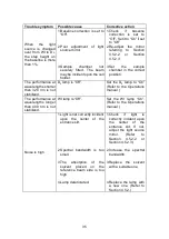
Trouble symptom 

Possible cause 

Corrective action 

1.Baseline  correction  is  set  to 

“Off”. 


1.Check 

if 

baseline 

correction  is  set  to 
“Off”. Set it to “On” if set 
to “Off”. 

2.Poor  adjustment  of  light 

source mirror. 

2.Re-adjust  the  mirror 

referring 

to 

Section 

4.5.2.2 

or 

Section 

4.5.2.3. 


When 

the 

light 

source  is  changed 
over  from  WI  to  D

2

the  step  height  on 
the baseline is more 
than 1%. 

3.Sample 

chamber 

not 

securely  fitted.  The  beam 
may be incident upon the cell 
holder. 

3.Set 

the 

sample 

chamber  in  the  correct 
position. 

The  performance  at 
wavelengths shorter 
than  320  nm  is  not 
stabilized. 

D

2

 lamp is “Off”. 

Set  the  D

2

  lamp  to  “On” 

(Refer  to  the  Operations 
manual.) 

The  performance  at 
wavelengths  longer 
than  400  nm  is  not 
stabilized. 

WI lamp is “Off”. 

Set  the  WI  lamp  “On”. 
(Refer  to  the  Operations 
manual.) 

1.Light is not correctly incident 

upon  the  center  of  the 
entrance slit. 


1.Check 

if 

light 

is 

correctly  incident  upon 
the 

center 

of 

the 

entrance  slit.  If  not, 
adjust  the  light  source 
mirror. 

(Refer 

to 

Section 

4.5.2.2 

or 

Section 4.5.2.3.) 


2.Spectral  bandwidth  is  too 

small. 

2.Increase  the  spectral 

bandwidth. 


3.The 

absorption 

of 

the 

solvent 

placed 

on 

the 

reference  beam  side  is  too 
high. 


3.Replace  the  solvent 

with a suitable one. 

Noise is high. 

4.Lamp deteriorated. 

4.Replace  the  lamp  with 

a  new  one.  (Refer  to 
Section 4.5.2.) 


Содержание V-530

Страница 1: ...P N 0302 0256B November 2000 Model V 530 550 560 570 UV VIS Spectrophotometer Hard ware Function Manual...

Страница 2: ...symbol refer to the instrument manuals to protect the instrument against damage WARNING A WARNING indicates a potentially hazardous situation which if not avoided could result in serious injury or eve...

Страница 3: ...GROUND Figure 1 Warning Labels on the V 530 Rear Panel WARNING FOR CONTINUED PROTECTION AGAINST RISK OF FIRE REPLACE ONLY WITH FUSE OF THE SPECIFIED TYPE AND CURRENT RATINGS Only use fuses of the desi...

Страница 4: ...Rear Panel 2 Warning for carrying These instruments weigh as follows V 530 16 0 kg V 550 30 5 kg V 560 32 0 kg V 570 33 0 kg When carrying the instrument hold the carrying handle at the bottom of the...

Страница 5: ...missions equipment input current up to and including 16A per phase IEC61010 1 Safety requirements for electrical equipment for measurement control and laboratory use Part 1 General requirements A Decl...

Страница 6: ...Before using the instrument please read this instruction manual carefully and make sure that the contents are fully understood This manual should be easily accessible to the operator at all times duri...

Страница 7: ...cy The instrument may not function properly when near a strong magnetic field or high frequency source 8 Avoid vibration from vacuum pumps electric motors processing equipment and machine tools 9 Avoi...

Страница 8: ...party Disclosure of confidential information regarding software Modification of software Use of software on multiple workstations network terminals or by other methods not applicable under a network l...

Страница 9: ...BLE PARTS NOT SUPPLIED BY AN AUTHORIZED JASCO DISTRIBUTOR 5 CORROSION DUE TO THE USE OF IMPROPER SOLVENTS SAMPLES OR DUE TO SURROUNDING GASES 6 ACCIDENTS BEYOND JASCO S CONTROL INCLUDING NATURAL DISAS...

Страница 10: ...Electrical System 7 2 2 V 550 560 570 Spectrophotometers Optical System 9 2 2 1 Optical System 9 2 2 2 Electrical System 11 3 Nomenclature and Functions of Components 12 3 1 V 530 Spectrophotometer O...

Страница 11: ...ne Flatness 24 4 4 2 Wavelength Repeatability 25 4 4 3 Wavelength Accuracy 26 4 5 Replacement of Consumables 27 4 5 1 Replacement of Fuse 27 4 5 2 Lamp Replacement and Adjusting the Light Source Mirro...

Страница 12: ...hotometric mode Abs T R Photometric range 2 000 to 3 000 Abs 0 to 200 T Photometric display 10000 T 2 to 5 Abs Four digits and symbol Photometric repeatability 0 001 Abs 0 to 0 5 Abs 0 002 Abs 0 5 to...

Страница 13: ...Deuterium lamp 190 to 350 nm Halogen lamp 330 to 900 nm Light source changeover wavelength Any wavelength between 330 and 350 nm can be selected Wavelength range 190 to 900 nm Wavelength repeatabilit...

Страница 14: ...ght 460 W 595 D 260 H mm excluding protrusions 30 5 kg Note Photometric repeatability photometric accuracy and baseline flatness are the values obtained more than one hour after the Power switch is tu...

Страница 15: ...power when temperature variation is within 5 C wavelength 250 nm response Slow and spectral bandwidth 2nm Baseline flatness 0 001 Abs value obtained after baseline correction when temperature variati...

Страница 16: ...region 0 3 to 3 Abs NIR region Photometric display 0 0 to 200 0 T 2 to 5 Abs Four digits and symbol Displays up to 000 0 T and 0 000 Abs Photometric repeatability 0 001 Abs 0 to 0 5 Abs 0 002 Abs 0 5...

Страница 17: ...elength 850 to 2500 nm spectral bandwidth 8 nm Detector Photomultiplier tube Pbs photoconductive cell Power requirements 100 115 200 220 230 240 V 10 180 W Dimensions and weight Main unit 460 W 595 D...

Страница 18: ...the reference sample such as a solvent The light that has passed through the sample and the reference sample is alternately incident upon the silicon photodiode D D Ref Sam F G WI M5 M2 M BS 3 S2 S1 D...

Страница 19: ...rial 2 Accessory input Sccessory output Coarse Adj Fine Adj Detector Amp Battery Main unit 320 240 10 6 CPU ROM RAM I O I O LCD ROM Card RAM Card Autozero Goto WL File Start Stop Print iRM Touch key L...

Страница 20: ...and Halogen WI lamp 340 to 2500 nm for use in the VIS NIR region The light from the light source is converged and enters the monochromator It is dispersed by the grating in the monochromator and the l...

Страница 21: ...Light source M Mirror S Slit F Filter G Grating M8 beam splitter PM Detector Sam Sample beam Ref Reference beam W window WI D2 Light source M Mirror S Slit F Filter G Grating M8 beam splitter PM UV V...

Страница 22: ...and enters the microcomputer The signal processed by the microcomputer is displayed on the output device as digital data or a spectrum Light source changeover wavelength drive slit drive filter drive...

Страница 23: ...lid to open and gain access to the reference and sample cell holders The cell holder closest to the front of the instrument is the sample cell holder Fixing screws Fixes the sample chamber in positio...

Страница 24: ...emote module power cable Printer Connector for connecting the printer plotter cable Serial A Connector for connecting the communication cable to DS or iRM Serial B Connector for connecting theRS 232C...

Страница 25: ...reference and sample cell holders The cell holder closest to the front of the instrument is the sample cell holder Fixing screws Fix the sample chamber in position To mount the optional sample chambe...

Страница 26: ...ime lag fuses iRM PS Accepts the remote module power cable Serial A Connector for connecting the communication cable to DS or iRM Serial B Connector for connecting the RS 232C cable Recorder Terminal...

Страница 27: ...tion Fixing screws Fix the sample chamber in position To mount the optional sample chamber loosen these screws and remove the standard sample chamber Sample cell holder Mount the cell containing the s...

Страница 28: ...for operating the monochromator printer etc Stop Press to stop measurement Print Press to print out data measurement parameters etc File Press to save load parameters and data GotoWL Press to move to...

Страница 29: ...ete remove the sample from the sample chamber 4 2 Cleaning the Sample Chamber If a sample is spilt in the sample chamber quickly wipe up the spillage with gauze or similar material remove the sample c...

Страница 30: ...nual Baseline flatness Refer to Section 4 3 1 Wavelength repeatability Refer to Section 4 3 2 Wavelength accuracy Refer to Section 4 3 3 4 3 1 Baseline Abs 0 line Flatness This check should be perform...

Страница 31: ...thin the following criterion V 530 criterion Within 0 001 Abs 1000 200 nm V 550 560 570 criterion Within 0 001 Abs 850 200 nm Figure 4 1 Baseline flatness V 550 560 570 4 3 2 Wavelength Repeatability...

Страница 32: ...ing Speed 10 nm min End 654 nm Start 658 nm Data Pitch 0 1 nm End 654 nm Display 0 100 Data Pitch 0 025 nm No of Cycles 3 Display 0 100 Cycle Time 1 sec PMT Voltage 300 V No of Cycles 3 Cycle Time 1 s...

Страница 33: ...1 in Section 4 3 2 2 Start Spectrum Measurement from the Spectra Manager window and set the following parameters Parameters for spectrum with an emission line at 656 1 nm V 530 measurement parameters...

Страница 34: ...emission line at 656 1 nm Figure 4 6 D2 lamp spectrum with emission line at 486 0 nm 4 Wavelength accuracy is normal if the measurement result in within the following criteria V 530 criteria Within 65...

Страница 35: ...rument on 1 Select Spectrum from the main menu and measure the baseline of the entire region after setting the following parameters Refer to Section 5 4 of the Operations manual Response Medium Scanni...

Страница 36: ...following parameters V 530 measurement parameters V 550 560 570 measurement parameters Phtmtrc mode Sam Phtmtrc mode Sam Response Fast Response Fast Start WL 658 nm Band width 0 5 nm End WL 654 nm St...

Страница 37: ...nterval 0 1 nm End WL 654 nm Scan speed 40 nm min Data interval 0 025 nm No of Cycles 1 Scan speed 10 nm min Lower scale 0 No of Cycles 1 Upper scale 100 Lower scale 0 Upper scale 100 HT Voltage 300 V...

Страница 38: ...om the outlet before replacing a fuse Use the following procedure when replacing a fuse 1 Turn off the power and unplug the AC power cable from the outlet 2 Insert a flat headed screwdriver into the f...

Страница 39: ...he screws required for lamp replacement 2 When handling the lamp ware clean cloth gloves Never handle the lamp with bare hands 3 Never touch the mirror or any other optical elements by hand 4 If the l...

Страница 40: ...ce unit V 550 560 570 Replacement of Deuterium lamp 1 Slide the outer lid of the light source unit to remove it and then remove the inner lid Fig 4 8 2 Pull out the Deuterium lamp from the socket Fig...

Страница 41: ...nstrument 2 Start Time Course Measurement from the Spectra Manager window and set the following parameters V 530 measurement parameters V 550 560 570 measurement parameters Photometric mode Sample Pho...

Страница 42: ...ed if the beam from the lamp is not correctly incident upon the entrance slit troubles will arise such as lack of luminous energy bend of the baseline and deviation of the measurement value Whenever t...

Страница 43: ...uterium lamp 1 Turn on the instrument 2 Select Envir from the main menu to display the Environment menu 3 Select Single Beam from the Environment menu to display the single beam measurement screen Ref...

Страница 44: ...ete description of the problem When checking the instrument observe the following warnings and cautions WARNINGS 1 Do not directly look at the light ultraviolet light emitted from the Deuterium lamp a...

Страница 45: ...cal JASCO distributor WI lamp does not light Lamp burnt out Check the WI lamp to see if it has burnt out Replace the lamp with a new one if burnt out Refer to Section 4 5 2 D2 lamp does light Lamp bur...

Страница 46: ...r than 320 nm is not stabilized D2 lamp is Off Set the D2 lamp to On Refer to the Operations manual The performance at wavelengths longer than 400 nm is not stabilized WI lamp is Off Set the WI lamp O...

Страница 47: ...36...

Страница 48: ...JASCO Corporation 2967 5 Ishikawa machi Hachioji shi TOKYO JAPAN Printed in Japan...

Отзывы: