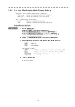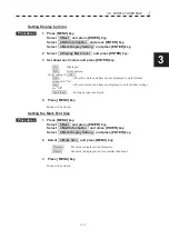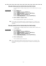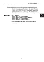
3-28
3.6
DISPLAY
USER
MAP
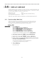
Navigation information such as a maximum of 256 points of NAV lines, coastlines, depth contours, and
NAV marks can be displayed, created, read, saved, corrected, and deleted. (This function is available
only when navigation equipment is connected to this radar system.)
Marks that can be used
: 29 types
Lines that can be used
: 3 types (solid, broken, and dashed-dotted line)
Color of mark and line that can be used
: 7 colors
If radar video is poor visibility caused by user map function, turn the map displays temporarily off.
3.6.1 Create User Map (Mark/ Line)
In this system, when the radar is in the transmission state, the user map is displayed all the time.
However, valid latitude / longitude data and true bearing data must be entered into the system.
The user map can be created and edited by performing the following operation.
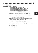
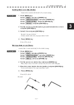
Plotting a Mark
Procedures
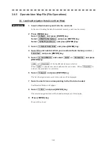
1 Press [MENU] key .
Select 8.Next and press [ENTER] key.
Select 4.NAV Information and press [ENTER] key.
Select 1.Edit User Map and press [ENTER] key.
Select 1.Make with cursor and press [ENTER] key.
It is possible to make with latitude / longitude by selecting 2.Make with L/L .
2 Set the type of mark with 1.Type and press [ENTER] key.
3 Set the color of mark with 2.Color and press [ENTER] key.
4 Put the cursor on a location of the display at which you want to plot
the mark, and press [ENTER] key.
The specified mark is displayed in the specified shape and color.
To create another mark, repeat the above procedures.
5 Press [ MENU] key.
Menu will be closed.
Содержание JMR-611
Страница 2: ......
Страница 24: ......
Страница 26: ......
Страница 28: ......
Страница 33: ...1 5 1 1 4 EXTERIOR DRAWINGS y Fig 1 1 Exterior Drawing of Scanner Unit Type NKE 387 Unit mm...
Страница 34: ...1 6 Fig 1 2 Exterior Drawing of Processing Unit Type NDC 1774 Unit mm...
Страница 35: ...1 7 1 1 4 EXTERIOR DRAWINGS y Fig 1 3 Exterior Drawing of Operating Unit Type NCE 5923 Unit mm...
Страница 38: ......
Страница 54: ......
Страница 116: ......
Страница 118: ......
Страница 124: ......
Страница 134: ......
Страница 136: ......
Страница 142: ......
Страница 144: ......
Страница 154: ......
Страница 156: ......
Страница 160: ......
Страница 164: ......
Страница 166: ......
Страница 172: ......
Страница 174: ......
Страница 177: ...APPENDIX Fig 1 Block Diagram of JMR 611...
Страница 181: ...APPENDIX Fig 5 Internal Connection Diagram of Control Unit NCM 994...
Страница 182: ......
Страница 184: ......
Страница 186: ......
Страница 187: ......

