


7-4
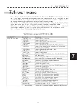
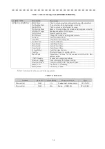
Table 7-2 Alarm message list (GENERAL WARNING)
ALARM TYPE
MASSAGE
Description
GENERAL WARNING
MAX Point
Tried to enter navigation information beyond the specified.
No Heading Data
N-up selection when bearing data is invalid.
Invalid Data
Tried to enter any data beyond its range.
No Position Data
Mark or line input when the latitude and longitude is invalid.
AIS MAX Target
Maximum number of AIS targets.
Not Allowed
General operation error.
POSN Reset
Change the latitude and longitude sentence.
No Card
Card: Not detected yet.
Card Full
Card: Run out of free space.
Invalid Card
Card: Invalid card.
Read Failed
Card: Read failure.
Write Failed
Card: Write failure.
Erase Failed
Card: Erase failure.
Format Failed
Card: Unformatted card.
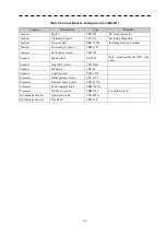
Copying Displayed-image is capturing to file.
Slave Mode
Operation of a menu for the scanner unit when the slave
mode is active.
TXRX Standby
Scanner unit completes pre-heat.
Situation Change Under
changing the Situation Pattern.
Situation Restore
Complete setting of the Situation Pattern.
Battery Low
The battery is weakening.
Battery Dead
The battery is dead.
Table 7-3 shows a list of fuses used in the equipment.
Table 7-3 Fuse List
Location
Parts No.
Current Rating
Protection Circuit
Type
Process Unit
F401
5A
Scanner unit without motor
ST4-5AN1
Process Unit
F402
10A
Motor (CBP-202)
ST6-10AN1
Содержание JMR-611
Страница 2: ......
Страница 24: ......
Страница 26: ......
Страница 28: ......
Страница 33: ...1 5 1 1 4 EXTERIOR DRAWINGS y Fig 1 1 Exterior Drawing of Scanner Unit Type NKE 387 Unit mm...
Страница 34: ...1 6 Fig 1 2 Exterior Drawing of Processing Unit Type NDC 1774 Unit mm...
Страница 35: ...1 7 1 1 4 EXTERIOR DRAWINGS y Fig 1 3 Exterior Drawing of Operating Unit Type NCE 5923 Unit mm...
Страница 38: ......
Страница 54: ......
Страница 116: ......
Страница 118: ......
Страница 124: ......
Страница 134: ......
Страница 136: ......
Страница 142: ......
Страница 144: ......
Страница 154: ......
Страница 156: ......
Страница 160: ......
Страница 164: ......
Страница 166: ......
Страница 172: ......
Страница 174: ......
Страница 177: ...APPENDIX Fig 1 Block Diagram of JMR 611...
Страница 181: ...APPENDIX Fig 5 Internal Connection Diagram of Control Unit NCM 994...
Страница 182: ......
Страница 184: ......
Страница 186: ......
Страница 187: ......