3-16
3.5
GENERAL
OPERATIONS
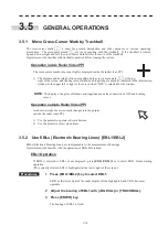
3.5.1 Move Cross-Cursor Mark by Trackball
The cross-cursor mark + is used for position designation and other purposes in various operating
procedures. The cross-cursor mark + moves in coupling with the trackball. If the trackball is rotated
up and down or right and left, the cross-cursor mark follows the move of the trackball.
Operators must be familiar with trackball operation before running the system.
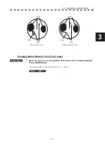
Operation inside Radar Video PPI
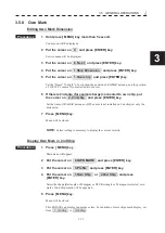
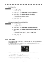
The cross-cursor mark as shown at right is displayed inside the radar video PPI.
1) The distance and bearing between own ship and the cross-cursor mark + at the top
right of the screen, and the degrees of latitude and longitude are digitally indicated in the information
window at the upper left or right of the screen when “GPS” is selected for the window.
NOTE:
The display of degrees of latitude and longitude needs the connection of GPS and heading
sensor.
Operation outside Radar Video PPI
As shown at right, the cursor mark changes into the pointer
outside the radar video PPI.
1) Use the pointer to operate software buttons.
2) Use the pointer to select menu items.
3.5.2 Use EBLs (Electronic Bearing Lines)
[EBL1/EBL2]
EBLs (Electronic Bearing Lines) are indispensable to the measurement of bearings.
Operators must be familiar with the operation of EBLs beforehand.
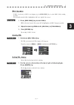
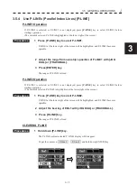
EBL1 Operation
If EBL2 is selected or EBL1 is not displayed, press
[EBL1/EBL2]
key to select EBL1 before starting
operation.
(The currently selected EBL is highlighted at the lower right of the screen.)
Procedures
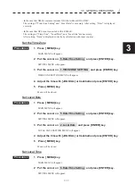
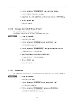
1 Press [EBL1/EBL2] key to select EBL1.
EBL1 at the lower right of the radar display will be highlighted, and EBL1 becomes
operable.
2 Adjust the bearing of EBL1 with [JOG DIAL] or [TRACKBALL].
3 Press [ENTER] key.
The bearing of EBL1 is fixed .
Содержание JMR-611
Страница 2: ......
Страница 24: ......
Страница 26: ......
Страница 28: ......
Страница 33: ...1 5 1 1 4 EXTERIOR DRAWINGS y Fig 1 1 Exterior Drawing of Scanner Unit Type NKE 387 Unit mm...
Страница 34: ...1 6 Fig 1 2 Exterior Drawing of Processing Unit Type NDC 1774 Unit mm...
Страница 35: ...1 7 1 1 4 EXTERIOR DRAWINGS y Fig 1 3 Exterior Drawing of Operating Unit Type NCE 5923 Unit mm...
Страница 38: ......
Страница 54: ......
Страница 116: ......
Страница 118: ......
Страница 124: ......
Страница 134: ......
Страница 136: ......
Страница 142: ......
Страница 144: ......
Страница 154: ......
Страница 156: ......
Страница 160: ......
Страница 164: ......
Страница 166: ......
Страница 172: ......
Страница 174: ......
Страница 177: ...APPENDIX Fig 1 Block Diagram of JMR 611...
Страница 181: ...APPENDIX Fig 5 Internal Connection Diagram of Control Unit NCM 994...
Страница 182: ......
Страница 184: ......
Страница 186: ......
Страница 187: ......

