www.janitza.de
UMG 96-PA
47
13. 4. 1 Phasor diagram basics
The phasor diagram graphically describes
the phase shift / phase angle between the
voltage and the current. The pointer rotates
around an origin point at a constant speed -
proportionally to the frequency of the voltage
and the current. The pointer diagram there-
fore describes the current
status of the quantities in an alternating cur-
rent circuit.
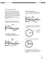
Representation of Ohmic resistance:
• Voltage and current have the same phase
u
i
u
i
u
i
Representation of inductance:
• The voltage rushes ahead of the current
• In an "ideal coil," the phase shift is 90°
u
i
u
i
u
i
Representation of capacity:
• The current rushes ahead of the voltage
• In an "ideal condenser," the phase shift is
90°
u
i
u
i
u
i
In a combination of states, the phase angle
"current to voltage" values can range from
-90° to +90°.
U
I
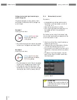
Current:
Display with
short pointers
Voltage:
Display with
long pointers
Example of a phasor diagram (3-phase)
UL1
IL1
IL2
UL2
UL2
IL3
The voltage and the current are pushed
against each other. The current rushes ahead
of the voltage, i.e. the network has a capaci-
tive load.
Содержание UMG 96-PA
Страница 7: ...www janitza de UMG 96 PA 7 ...
Страница 67: ...www janitza de UMG 96 PA 67 ...
Страница 81: ...www janitza de UMG 96 PA 81 ...

