UMG 96-PA
www.janitza.de
16
5.
Installation
5. 1
Installation site
The device is suitable for installation in
non-mobile and weather-protected control
panels in indoor environments.
Plan on an earth for conducting control pan-
els.
5. 2
Installation position
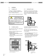
The cut-out dimensions of the control panel
are 92
+0,8
mm x 92
+0,8
mm.
To achieve sufficient ventilation, take the
following measures:
• Install the device vertically.
• Maintain a minimum clearance of 50 mm
above and below.
• Maintain a minimum clearance of 20 mm
on each side.
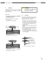
Fig. Back view of the installation posi-
tion of the UMG 96-PA
m
CAUTION!
Material damage may
result if the installation in-
structions are not followed!
Not following the installation instructions
may damage or destroy your device.
Comply with the details on the installation
position in sections „Installation“ and
„Technical Data“.
5. 3
Securing the device
The device is secured in the control panel
with the side mounting brackets. The brack-
ets are to be removed e.g. using a screw-
driver as a horizontal level before the device
is put in.
Fig. Side view of UMG 96-PA with mounting brackets.
The brackets can be loosened by leveraging them hori-
zontally with a screwdriver.
Assembly plate
Clamping screw
Screwdriver
Mounting
brackets
Once the clamping screws
touch the surface of the
assembly plate: use two further
rotations at most to secure
the device
Then slide in and snap the brackets into
place, and finally screw in the screws to se-
cure the device.
• Turn the clamping screws until they just
touch the assembly plate.
• Then tighten the clamping screws with two
more rotations each (the mounting brack-
ets may be destroyed if the screws are
tightened too much).
Содержание UMG 96-PA
Страница 7: ...www janitza de UMG 96 PA 7 ...
Страница 67: ...www janitza de UMG 96 PA 67 ...
Страница 81: ...www janitza de UMG 96 PA 81 ...

