Issue: 01.07.2020
Page 16
Installation
Electrical
Cable type and sizing must be selected for the particular application and the electrical installation should
conform to the current local standards.
•
Cables to the indoor units
should be routed through the ‘U’ shaped cut
-out in the bottom of the removable air grille at
the side of the units and into the rear of the electric box.
•
Cables to the outdoor unit should be routed through the cable glands on the rear of the unit.
•
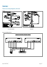
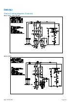
Connect the mains supplies as per the wiring diagrams on pages
27 & 28-29.
Access to the electrical terminals and components on the indoor unit is via the removable cover plate on the front of the unit.
Removal of the cover plate gives access to the contactor, the terminal block as well as the electronic controller and rocker switch
connections.
To gain access to the electrical box on the outdoor unit, remove the screws of the panel located on the right hand side of the unit
and remove the panel. The electrical box is located behind the panel.
Important Note:
The mains electrical supply to the indoor units must be via a suitably rated isolator and circuit breaker
or fuse. There is no isolator fitted to the indoor units. The rocker switch on the front of the indoor
units is for isolating the indoor fan and electronic controller only. The mains electrical supply to the
outdoor unit must be via a suitably rated motor rated circuit breaker or fuse and requires termination
at a suitably rated isolator. There is no isolator fitted to the outdoor units.
J & E Hall cellar systems require a 230V/1/50 supply to the indoor units and either a 230V/1/50 or a
400V/3/50 supply to the outdoor unit (depending on outdoor unit model chosen). They are not
suitable for any other supply voltages (other than a deviation of +/- 10% of the above values) and are
not suitable for 60 Hz supplies.
Содержание Cellar Plus 70-S1
Страница 1: ...CELLAR PLUS CELLAR COOLER RANGE ISSUE 01 07 2020 CELLAR COOLER RANGE TECHNICAL MANUAL...
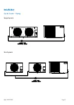
Страница 8: ...Issue 01 07 2020 Page 8 Installation Quick Guide Piping Single System Twin System...
Страница 24: ...Issue 01 07 2020 Page 24 Drawings Dimensional drawings Indoor Unit 80E...
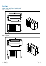
Страница 25: ...Issue 01 07 2020 Page 25 Drawings Dimensional drawings Outdoor Units BSCU 30 M1 M3 BSCU 35 M1 M3...
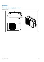
Страница 26: ...Issue 01 07 2020 Page 26 Drawings Dimensional drawings Outdoor Units BSCU 40 M1 M3...
Страница 28: ...Issue 01 07 2020 Page 28 Drawings Electrical wiring diagrams Outdoor BSCU 30 M1 BSCU 35 M1 BSCU 40 M1...
Страница 29: ...Issue 01 07 2020 Page 29 Drawings Electrical wiring diagrams Outdoor BSCU 30 M3 BSCU 35 M3 BSCU 40 M3...
Страница 33: ...Issue 01 07 2020 Page 33 Certification...
Страница 34: ...Issue 01 07 2020 Page 34 THIS PAGE IS LEFT BLANK INTENTIONALLY...


