


Notes on EMC
7 Notes on EMC
7.1 Aluminum
Version
The CAN-bus connected to the CANbridge must have a shielded lead. The shield
braiding is to be laid flat on the connector housing.
The shield connections of CAN1 (X3), CAN2 (X4), serial interface (X2) and power
supply (X1) are connected with one another in the device
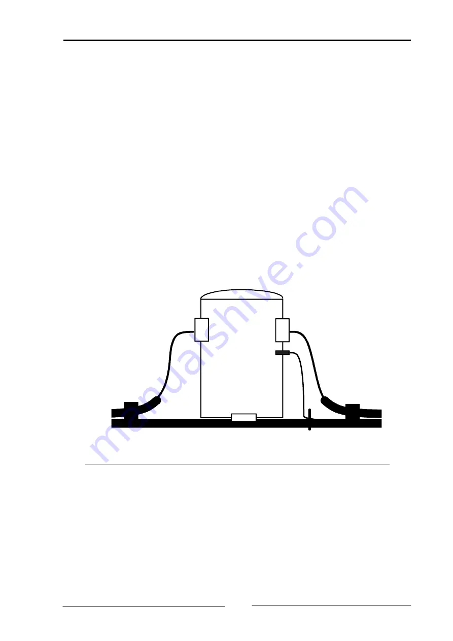
7.2 Industrial DIN-Rail Version – Shield concept
The highest interference immunity is achieved when the shield of the two CAN
buses is grounded on the assembly plate and the ground terminal (Pin 1 / PE,
FASTON 6,3 x 0,8 mm) of the CANbridge is connected to the next available
grounding (see Fig. 7-1). Via parallel connection of a resistor (1 M
Ω
) and a ca-
pacitor, the grounding connection is connected internally to the GND of CAN1,
CAN2 and of the supply voltage.
CANbridge
C
AN2
C
AN1
PE
Fig. 7-1: Shield concept CANbridge Industrial DIN-Rail
Copyright IXXAT Automation GmbH
CANbridge - Manual, V1.4
27