


5: System Configuration
○
○
○
○
○
○
○
○
○
○
○
○
○
○
○
○
○
○
○
○
○
○
○
○
○
○
○
○
○
○
○
○
○
○
○
○
○
○
○
○
○
○
○
○
○
○
○
○
○
○
User’s Manual
5•5
○
○
○
○
○
○
○
○
○
○
○
○
○
○
○
○
○
○
○
○
○
○
○
○
○
○
○
○
○
○
○
○
○
○
○
○
○
○
○
○
○
○
○
○
○
○
○
○
○
○
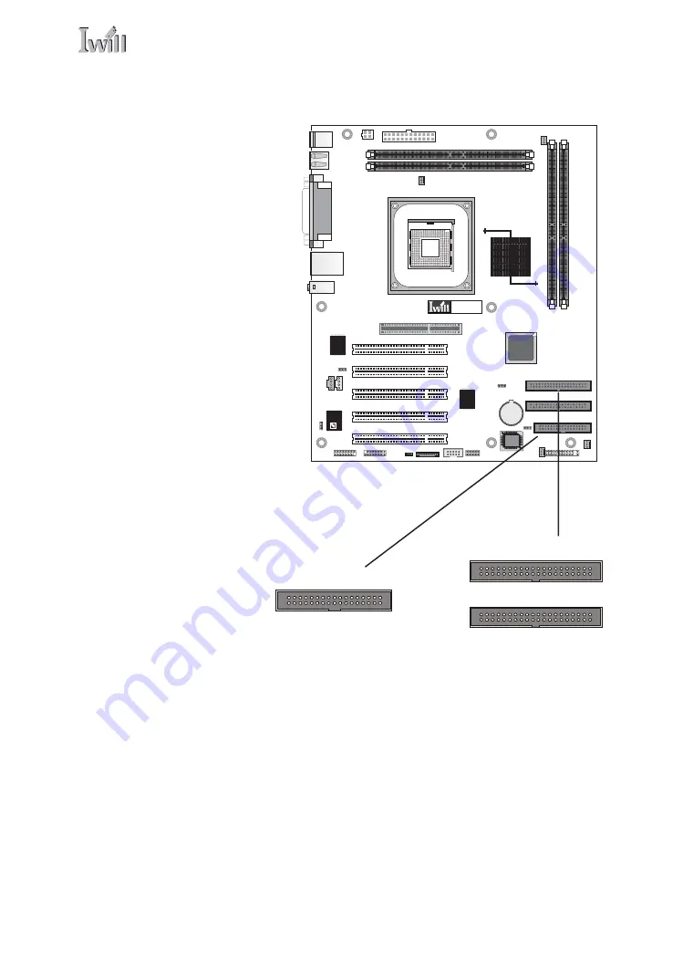
mPGA478B
C3DX HSP56
CMI8738
LAN
Controller
S
M
A
R
T I/O
RIMM(J6)
RIMM(J5)
RIMM(J3/J4)
IDE1(J29)
IDE0(J28)
FDD(J30)
Front Panel(J43)
J41
J42
IR(J45)
SMART CARD
(J59)
MS CARD(J60)
J46
SPDIF(J61)
GAME PORT
(J78)
(JP8)
CD_IN
(J54)
AUX_IN(J53)
JP17
PCI(J12)
PCI(J13)
PCI(J14)
PCI(J15)
PCI(J16)
JP6
JP16
AGP(J11)
P4R533-N
J39
ATX 12V(J37)
J37A
J40
Onboard IDE Connectors
Each channel connector
supports one IDE channel
with two drives, a Master
and a Slave. The Master
drive connects to the con-
nector on the end of the
ribbon cable. The Slave
drive connects to the con-
nector in the middle of
the ribbon cable.
Note:
The ribbon cable used
must support the transfer
mode of the fastest device
connected to it to avoid
degraded performance.
Floppy connector
IDE0 Primary Channel
IDE1 Secondary Channel
Floppy Drive Connector
The floppy drive connec-
tor supports two floppy
disk drives. The first drive,
Drive A:, connects to the
connector on the end of
the floppy drive connec-
tor cable. A second drive,
Drive B:, would connect to
the middle connector on
the cable although sys-
tems now commonly only
have one floppy disk drive.
Содержание P4R533
Страница 1: ...IWILL P4R533 P4R533 N Motherboard User s Manual...
Страница 2: ...P4R533 P4R533 N Motherboard User s Manual II...
Страница 14: ...P4R533 P4R533 N Motherboard User s Manual 1 6...
Страница 46: ...P4R533 P4R533 N Motherboard User s Manual 3 10...
Страница 69: ...5 System Configuration User s Manual 5 9 CMOS Setup Utility Interface commands...
Страница 71: ...5 System Configuration User s Manual 5 11 CMOS Setup Utility Main Screen...
Страница 82: ...P4R533 P4R533 N Motherboard User s Manual 5 22...
Страница 88: ...P4R533 P4R533 N Motherboard User s Manual 5 28...
Страница 100: ...P4R533 P4R533 N Motherboard User s Manual 6 12...