S p e z i a l e l e k t r o n i k G m b H
iseg
c/o ROTECH
Email: [email protected]
Phone ++ 49 351 / 26 95 - 260
Spezialelektronik
Bautzner Landstr. 45
http://www.iseg-hv.com
Fax
++ 49 351 / 26 95 - 261
GmbH
D - 01454 Rossendorf
Germany
21
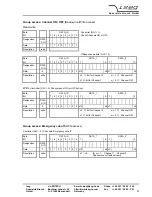
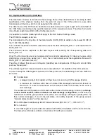
Group access: ADC filter frequency setting
(Read-write/Write access)
(Programmable ADC conversion time = 1 / f
N
, f
N
... filter first notch frequency)
Read-write
Byte
DATA_ID
Controller (DLC = 1):
Bit
7
6
5
4
3
2
1
0
Read actual ADC filter frequency f
N
Designation
DATA
_DIR
- If all channels are stable then this ADC filter frequency f
N
is active
Data
1
1
1
1
1
0
0
0
0
- If V
O
is ramping at least one channel then the ADC filter
Description
read
frequency is f
N
= 100 Hz
⇓
Response module (DLC = 3)
Byte
DATA_ID
DATA_1
DATA_0
Bit
7
6
5
4
3
2
1
0
7
...
0
7
0
Designation
DATA
_DIR
Data
0
1
1
1
1
0
0
0
0 x15
x8 x7
...
x0
Description
write
ADC filter frequency f
N
= 19200 / (x15 ... x0) [Hz]
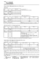
Write
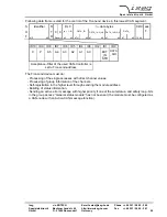
(Controller [DLC = 3]: Write new ADC filter frequency f
N
)
Byte
DATA_ID
DATA_1
DATA_0
Bit
7
6
5
4
3
2
1
0
7
0
7
6
5
4
3
2
1
0
Designation
DATA
_DIR
LSB
Data
0
1
1
1
1
0
0
0
0 x15
x8 x7
x0
Description
write
(x15 ... x0) = 19200 / ADC filter frequency f
N
[Hz]
with 5 Hz
≤
f
N
≤
100 Hz (invalid f
N
will be ignored and the bit
‘Input-error’ in ‘Status channel’ is set).
- if all channels arrive at V
set
the first time, further
measurements are made with this filter frequency. I.e.:
V
set
will be compared to V
actual
averaging according to f
N
- factory setting: f
N
= 50 Hz


