


Maintenance and Storage
Revised October 2004
3800 Vital Signs Monitor Service Manual
11-3
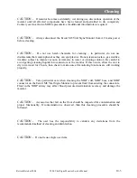
In order to prevent the Escort M8 Vital Signs Monitor’s risk current from increasing beyond safe
limits, the ECG cable should be cleaned according to the instruction in the Cleaning section of
this manual.
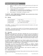
To place the Escort M8 Vital Signs Monitor back in service after maintenance has been
performed, connect the Escort M8 Vital Signs Monitor to a wall AC outlet, ensuring that cables
do not present a tripping hazard.
11.1 Battery Replacement
If the battery is no longer holding a charge, it may need to be replaced. This should only be done
by qualified service personnel.
To replace the battery:
1.
Purchase a replacement battery (see Accessories section for part number).
2.
Power-off the monitor.
3.
On the back of the monitor, disconnect the AC power cord.
4.
If
SureTemp
®
P L U S
is installed perform the following (if not continue to step 5):
•
Remove the
SureTemp
®
P L U S
Probe and Blue Probe Well from the
monitor.
•
Disconnect the
SureTemp
®
P L U S
connector from the connection located in
the center rear of the monitor.
5.
Remove the cover with the CE Mark as follows:
•
Hold the cover in place while removing the two screws from the top left
and right of the panel.
•
Once screws are removed, carefully rotate the panel toward the AC power
connector and lay flat on working surface.
Leakage Current
•
Connect to Safety Analyzer.
WARNING – FOLLOW SAFETY INSTRUCTIONS AS
INDICATED IN THE MANUAL FOR THE ANALYZER.
•
Verify Patient Lead Leakage (to ground): < 10 uA.
•
Verify Patient Lead Leakage (inter-lead): < 10 uA.
•
Verify Patient Lead Leakage (mains applied to leads): <
50 uA.
•
Verify Leakage to ground (normal): < 500 uA.
•
Verify Leakage to ground (reversed polarity): < 1000 uA.
•
Verify Leakage to ground (neutral opened): < 1000 uA.
Di-electric Withstand
WARNING – FOLLOW SAFETY INSTRUCTIONS AS
INDICATED IN THE MANUAL FOR THE DI-ELECTRIC
WITHSTAND TESTER.
•
Connect ECG Leads and monitor power input to tester.
•
Apply 1500 Vdc for 1 second. No isolation breakdown
should be detected.
•
Connect monitor power supply input and output to tester.
•
Apply 1500 Vdc for 1 second. No isolation breakdown
should be detected.
Recorder
Verify strip chart recording of waveform data followed by a
parameter snapshot.
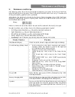
Monitor Function
Procedure
Содержание Escort M8
Страница 1: ......
Страница 2: ......
Страница 26: ......
Страница 32: ......
Страница 34: ......
Страница 44: ......
Страница 55: ...Repair Revised October 2004 3800 Vital Signs Monitor Service Manual 7 11 Figure 7 10 Input Panel Assembly View...
Страница 56: ...Repair 7 12 3800 Vital Signs Monitor Service Manual Revised October 2004 Figure 7 11 Recorder Subassembly View...
Страница 60: ......
Страница 66: ......
Страница 72: ......
Страница 78: ......
Страница 80: ......


