


Repair
7-14
3800 Vital Signs Monitor Service Manual
Revised October 2004
7.5
Monitor Disassembly Procedure
1.
Disconnect the power cord from the monitor.
2.
Place the monitor face down on a padded surface.
3.
Remove the battery cover assembly (2 screws).
4.
Remove the battery (it lifts out).
5.
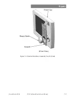
Detach the monitor rear case assembly from the monitor front bezel assembly (7
screws).
6.
Turn the monitor upright so that the display is facing towards you. Carefully
separate the front bezel from the rear case assembly.
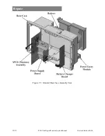
7.
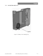
Disconnect the 2-wire speaker connector from the main board at J22.
8.
Disconnect the battery charger connector from the main board at J17.
9.
Disconnect the ground connection from the recorder board.
10.
Disconnect the SPO2 Masimo cable from the main board at J11.
11.
Disconnect the Masimo input cable from the SPO2 Masimo board at J1.
12.
Detach the front bezel assembly from the monitor rear case assembly.
7.6
Monitor Reassembly Procedure
The monitor can be reassembled by following the disassembly steps in reverse order as a guide.
Remember to functionally verify all monitoring functions before returning the monitor to service.
See chapter 5 for details.
A leakage current and di-electric withstand test should be performed if the monitor was
disassembled (see chapter 11 for details).
7.7
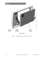
Replacing the Display
Before getting started, please refer to the figure that shows the monitor front bezel assembly view,
located earlier in this chapter.
1.
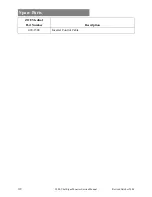
Obtain a replacement LCD display (see Spare Parts chapter).
2.
Disassemble the monitor according to the Monitor Disassembly Procedure. This
should be done in a static- and dust-free environment in order to maintain
cleanliness of the display lens.
3.
Remove the damaged display from the monitor front bezel assembly, being careful
not to scratch the lens that is mounted in front of the display.
4.
Install the new display. These screws should be backed-off until they line up with
the already-formed threads, in order to avoid stripping the threads. They should be
tightened to 3-4 inch-pounds (0.34-0.45 newton-meters).
7.8
Replacing the Optional Recorder Assembly
1.
After monitor disassembly is performed, remove the main board.
2.
Disconnect the recorder cable from the recorder board at J3.
3.
Disconnect the Masimo cable from the SPO2 Masimo board at J1, remove the
NBP hose from the NBP input connector behind the input board.
4.
Disconnect 2 plastic screws from the backside of the main board and remove the
input panel assembly with recorder assembly and input board attached.
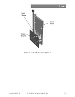
5.
Remove 4 screws securing the patient input board to the input panel assembly.
Содержание Escort M8
Страница 1: ......
Страница 2: ......
Страница 26: ......
Страница 32: ......
Страница 34: ......
Страница 44: ......
Страница 55: ...Repair Revised October 2004 3800 Vital Signs Monitor Service Manual 7 11 Figure 7 10 Input Panel Assembly View...
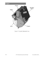
Страница 56: ...Repair 7 12 3800 Vital Signs Monitor Service Manual Revised October 2004 Figure 7 11 Recorder Subassembly View...
Страница 60: ......
Страница 66: ......
Страница 72: ......
Страница 78: ......
Страница 80: ......


