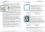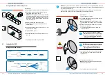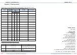
Stripping tool, screw driver, scissors or cutter
Prerequirement:
The weather protection hood is installed.
24
25
INSTALLATION AND ASSEMBLY
INSTALLATION AND ASSEMBLY
iV-Compact ventilation system
•
Installation and operating instructions
iV-Compact ventilation system
•
Installation and operating instructions
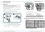
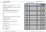
Electrical connection of the reversible fan
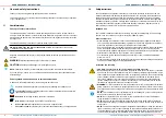
NOTE
Incorrect electrical connection.
Damage to the fan motor!
• Connect the ventilation unit to the mains via a controller.
• Observe the correct cable colour sequence at the socket and plug. If the colour sequence is
wrong, the fans will not start.
►
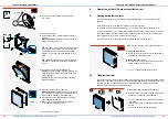
Insert inVENTron into the wall sleeve so that you
can reach the plug-in connection.
Ensure
that the fan's side
WITHOUT
type plate is
directed to the interior room side.
Ö
The thermal accumulator is inserted
4.6
Installing the thermal accumulator insert and connect the fan to the controller
Installing the thermal accumulator insert
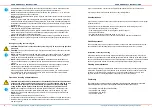
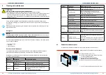
NOTE
Do not store/stack the thermal accumulator outside the wall sleeve.
This may cause dmage or breakage to the ceramic block!
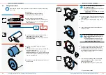
• Insert the thermal accumulator immediately after removing it from the packaging
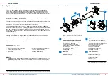
Requirement:
The weather protection hood is installed.
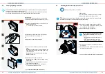
►
Remove the protective discs from the wall sleeve.
►
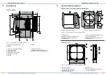
From the interior, slide the thermal accumulator
into the wall sleeve as far as the end-stop.
Make sure
that the handle is facing towards the
interior.
Make sure
that the controller cable (fan-BUS) is
facing towards the interior.
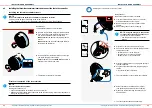
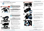
►
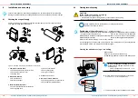
Trim the controller cable, 3-wire, to your deter-
mined wall thickness minus 140 mm.
►
Remove about 7 mm of the contoller cable's
sheath.
►
Remove the green socket from the plug.
NOTE
: Using the wrong wire end ferrules
to connect the strands in the socket
leads
to a short circuit in the fan-BUS!
• Use ferrules with collar to connect the
strands.
►
Align the socket's locking screws to the top.
►
Connect the three wires of the fan-BUS (controller
cable)to the socket:
• (White) wire III (–) to the left pole.
• (Gree) wire IV (+) to the centre pole.
• (Brown) wire V (–) to the right pole.
►
Align the locking screws on the plug and socket in
the same direction.
►
Plug the connected socket into the green plug on
the fan.
Ö
Extract air mode is adjusted.
Ö
The reversible fan is connected to the controller.
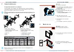
►
Select continuous ventilation mode (VENT).
(see operating instructions for the controller).
►
Make sure that all reversing fans rotate in the
same direction.
Ö
The functional test has been performed.
IV (+)
III (–)
V (–)
3 x 0.75 mm²


