4
5
USER AND SAFETY INSTRUCTIONS
USER AND SAFETY INSTRUCTIONS
iV-Compact ventilation system
•
Installation and operating instructions
iV-Compact ventilation system
•
Installation and operating instructions
1
User and safety instructions
Thank you for purchasing this high quality product from inVENTer!
This section provides an overview of the basic safety precautions for safe and proper operation
of your ventilation unit.
1.1
User information
Concept of safety instructions
The safety and warning instructions in these operating instructions have a uniform structure
and are marked with a symbol on the left side of the instruction. A signal word in front of the text
also indicates the hazard level. If several hazard levels exist, the highest level safety instruction
is always used.
The safety and warning instructions contain the following information.
SIGNAL WORD:
Type and origin of the hazard.
Possible consequences of the hazard!
•
Measures to avoid the hazard.
A signal word indicates the severity of the potential hazard unless the preventative measures
are taken.
WARNING
indicates possible danger of serious injury or death.
CAUTION
indicates possible danger of minor/significant injury.
NOTE
indicates: Imminent or possible damage to property due to an adverse event/state.
If you see this sign, ensure you observe the described measures to prevent possible hazards
and/or damage.
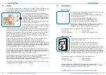
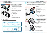
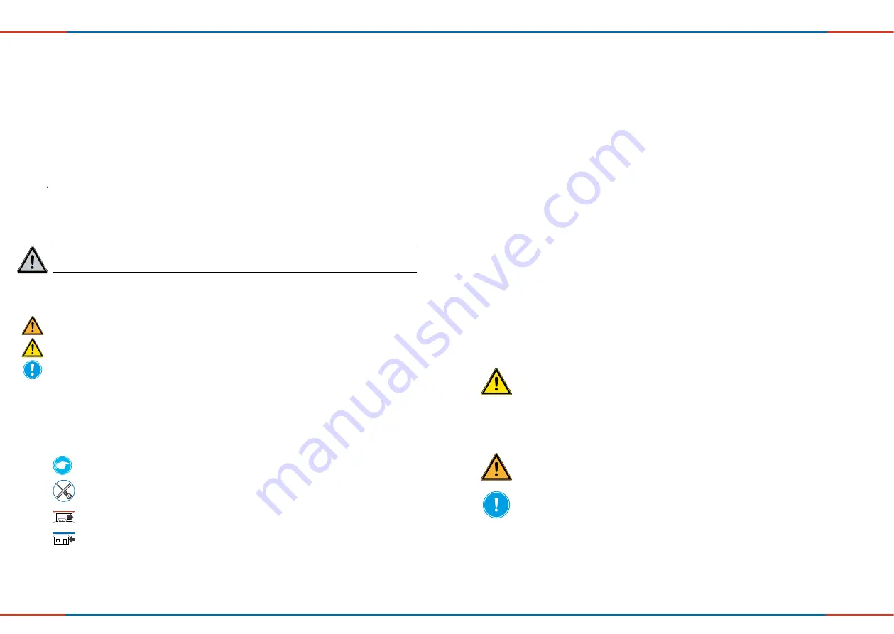
Other symbols and notices used in this documentation
In addition to the safety instructions, the following symbols are used:
A
TIP
symbol indicates practical and useful tips for handling the ventilation unit.
A
tool symbol
before an installation sequence lists any additional tools and materials
required for the described task.
Red frame
surrounding: Graphic shows the interior wall.
Blue frame
surrounding: Graphic shows the exterior wall.
►
Action required:
this requires the user to perform a specific action.
Check the results:
this requires you to check the results of the action you have performed.
1.2
Safety instructions
These installation and operation instructions are part of the ventilation unit and must be per-
manently available. When handing the equipment/system to a third party, the installation and
operation instructions must be handed over also. Before performing any work on the system,
read the installation and operation instructions carefully and observe all information regarding
installation, assembly, operation, cleaning and maintenance contained in this section. Also note
the safety instructions that precede the described handling instructions. Non-observance of
safety warnings could result in injury and/or property damage.
Intended use
The inVENTer ventilation units with heat recovery are used to ventilate living rooms and living
spaces. They are controlled by a control unit of the inVENTer system.
General instructions
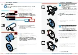
• When installing the unit/system, observe the applicable standards, regulations and directi-
ves. In particular, the applicable building regulations, fire protection regulations and accident
prevention regulations of the employers' liability insurance association.
• Use the unit/system only in accordance with the applications described in this documentation
and in the detailed installation and operating instructions and only in conjunction with the
components recommended, approved and named in this documentation by inVENTer GmbH.
•
Modifications or alterations to the unit/system are not permitted.
• Your ventilation system has been developed exclusively for use in ambient temperatures
within -20 – 50 °C.
• Proper and safe operation of the unit/system requires proper transport, storage and installati-
on as well as careful usage and cleaning/maintenance.
Installation and assembly
•
CAUTION: The system may only be installed by qualified personnel.
• Before starting the work, you should have a project plan which shows the number of ventilati-
on units, the position of the ventilation units, the ventilation principle (cross ventilation, single
room ventilation, exhaust ventilation) and the corresponding controllers. The exact positioning
of the individual ventilation units and control units must be checked by the customer and,
if necessary, adapted to the local conditions with the involvement of the responsible cons-
truction manager or the user. For optimum functionality, it is recommended that the unit be
installed at an appropriate location in the upper wall area.
• WARNING:
For joint operation with room air-dependent and room air-independent fireplaces,
safety measures must be taken to prevent the creation of a negative pressure in the building.
The responsible chimney sweep and/or construction manager decides which measures are to
be taken.
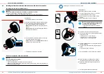
• NOTE:
The ventilation unit is not suitable for drying out buildings. Do not put it into operation
until the construction work has been completed.
• NOTE:
Do not install the unit in the vicinity of room air thermostats or in the immediate en-
vironment/above sensitive pictures or furniture.
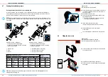
• NOTE:
Observe the specified minimum distances on both sides of the wall and frontally to
avoid unintentional mixing of outside and exhaust air and to ensure access to the unit and its
components.
• NOTE:
The wall mounting sleeve must be integrated into the building envelope (air resistance
layer) in such a way that it is open to diffusion on the outside and impermeable to diffusion on
the inside, taking account of structural specifications. Material for this must be provided by the
customer. After installing the wall installation sleeve, bring the wall structure back up to the


