3.2
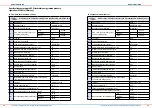
Position of the wall opening
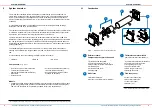
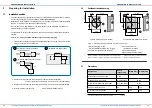
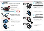
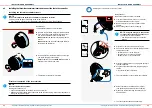
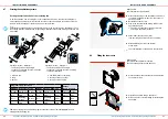
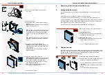
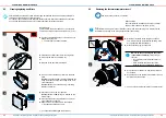
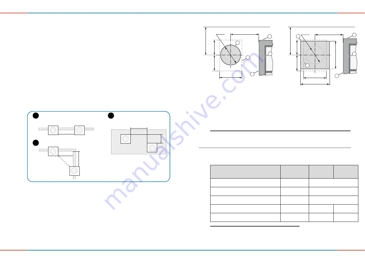
Figure 2: Dimension drawing: wall opening iV-Compact (Interior view)
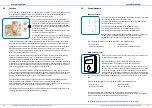
1)
Minimum distance to adjacent components on the interior wall side
3)
Attach weather protection hood at lintel height
2)
Minimum distance to adjacent components on the exterior wall side
4)
Observe insulation and shutters
Position wall opening (core drilling)
Position Simplex wall build-in system
12
13
PREPARING FOR INSTALLATION
PREPARING FOR INSTALLATION
iV-Compact ventilation system
•
Installation and operating instructions
iV-Compact ventilation system
•
Installation and operating instructions
3
Preparing for installation
3.1
Installation position
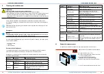
• The exact positioning of the ventilation units and controllers must be determined on-site and,
if necessary, adapted to the local conditions.
Consult your planner!
Installation is recommended in a suitable position in the upper wall area for optimal operation
(approx. room height 1.8 m [top edge of finished floor]).
• Do not place the unit near radiators, room thermostats or in the immediate vicinity/above
delicate furniture, surfaces or pictures.
• The ventilation unit must not be installed in areas in which direct contact with water spray is
possible.
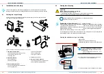
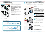
• Observe the following
minimum distances for the unit’s wall opening
:
1 between two ventilation units in push-pull operation (pair) in the same room to avoid the
mixing of outdoor air and exhaust air:
Horizontal or vertical installation
Installation with height offset:
(on the same wall):
Installation diagonally (over corners):
2 to adjacent components on the exterior wall (observe insulation/shutters):
Compact protective hood: 250 mm from hole center circumferentially
3 to adjacent components on the interior wall: 250 mm from hole center circumferentially
4 to frontal adjacent components:
300 mm for maintenance tasks
1,2 m
1,0 m
1,0 m
1,4 m
y
1,2 m – 0,75 y
1,2 m
1,0 m
1,0 m
1,4 m
y
1,2 m – 0,75 y
1,2 m
1,0 m
1,0 m
1,4 m
y
1,2 m – 0,75 y
A
B
C
Ø
180
134
142
≥
250
200
2
≥
250
≥
250
1,2)
260
249
1
134
142
200
5
≥
250
1,2)
5
4
3
1
4
3
Ø
160
2
1
Wall opening (fig. 2, left)
Simplex installation system (fig. 2, right)
2 Position of protective hood (contour)
3)
3 Door/window reveal
(insulation with render)
4 Door/window frame
5 Bottom edge of reveal (lintel)
4)
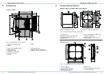
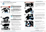
3.3
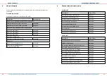
Dimensions
Designation
Depth/
length [mm]
Width [mm]
Height [mm]
Wall thickness with render [mm
> 140
Wall opening for wall sleeve
Wall thickness
1)
Ø 180
Wall sleeve R-D160x230 (285 / 495)
230 (285 / 495)
Ø 160
Compact protective hood
80
200
276
Flair inner cover V-233x233
61
2)
233
233
1)
incl. render, insulation, masonry and inner structure.
2)
opened


