


27
Connection to the Managed Switch requires UTP Category 5e network cabling with RJ-45 tips. For
more information, please see the Cabling Specification in Appendix A.
Step 5:
Supply power to the Managed Switch.
Connect one end of the power cable to the Managed Switch.
Connect the power plug of the power cable to a standard wall outlet.
When the Managed Switch receives power, the Power LED should remain solid Green.
2.2.2 Rack Mounting
To install the Managed Switch in a 19-inch standard rack, please follow the instructions described below.
Step 1:
Place the Managed Switch on a hard flat surface, with the front panel positioned towards the front side.
Step 2:
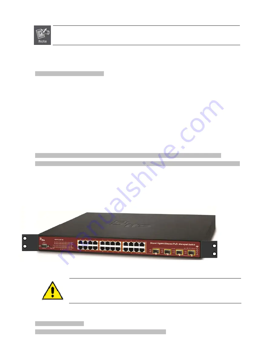
Attach the rack-mount bracket to each side of the Managed Switch with supplied screws attached to the package.
Figure 2-2-2
shows how to attach brackets to one side of the Managed Switch.
Figure 2-2-2:
Attach Brackets to the Managed Switch.
You must use the screws supplied with the mounting brackets. Damage caused to the parts by
using incorrect screws would invalidate the warranty.
Step 3:
Secure the brackets tightly.
Step 4:
Follow the same steps to attach the second bracket to the opposite side.
Содержание NS3702-24P-4S
Страница 1: ...NS3702 24P 4S User Manual P N 1072832 REV 00 01 ISS 14JUL14 ...
Страница 65: ...65 Buttons Click to apply changes Click to undo any changes made locally and revert to previously saved values ...
Страница 102: ...102 Figure 4 5 4 LACP Port Configuration Page Screenshot ...
Страница 119: ...119 Figure 4 6 4 VLAN Membership Status for Static User Page Screenshot ...
Страница 124: ...124 Figure 4 6 6 Private VLAN Membership Configuration page screenshot ...
Страница 135: ...135 VLAN 3 Port 3 Port 6 The screen in Figure 4 6 18 appears Figure 4 6 17 Private VLAN Port Setting ...
Страница 140: ...140 Figure 4 6 21 Group Name to VLAN Mapping Table Page Screenshot ...
Страница 164: ...164 Figure 4 8 2 Multicast Flooding ...
Страница 184: ...184 Figure 4 8 15 MLD Snooping Port Group Filtering Configuration Page Screenshot ...
Страница 204: ...204 Figure 4 9 6 QoS Egress Port Tag Remarking Page Screenshot ...
Страница 209: ...209 QoS Class QoS Class value can be any of 0 7 DPL Drop Precedence Level 0 1 ...
Страница 251: ...251 Figure 4 11 3 Authentication Method Configuration Page Screenshot ...
Страница 286: ...286 Figure 4 11 11 RADIUS Server Configuration Screenshot ...
Страница 290: ...290 Figure 4 11 17 Add User Properties Screen Figure 4 11 18 Add User Properties Screen ...
Страница 298: ...298 non committed changes will be lost ...
Страница 349: ...349 Figure 4 16 2 PoE Configuration Screenshot ...
Страница 355: ...355 Figure 4 16 5 PoE Status Screenshot ...


