21
8. COMPUTER SETUP
Turn on the computer. When the booting completes, the motors will be engaged
with the tracks. Select and quit Manual Mode repeatedly to see if the motors are
sufficiently disengaged all along the tracks and make the necessary height
adjustments. Make sure that the gap between the rollers and the tracks is not more
than 0.04" (1mm). Try to set the gap to the minimum safe distance, so there is no
intermittent drag along the tracks.
Go to Utilities->Preferences.
Set the motor engagement strength for each motor separately. Start with a lower
number, then increase the number and test the resistance of the motor in each
direction, until there is definite resistance everywhere.
The optimal settings range is 8...14 on the standard motors, 3...6 on the
SuperMotors. You need to raise the motor if the final setting is below the lower limit,
lower it if the setting is above the upper limit.
Go to Utilities->Measure/Calibrate
and calibrate the sensor wheels following the
on-screen instructions.
Go to System->Interface Setup/Test
.
Enter all the settings shown on the screenshot that was taped to the top of the box
containing the tablet and the docking station.
Ask the customer to set her/his preference for half or full cycle when the single
stitch switch is pushed. Set the Single Stitch Phase accordingly.
If the half stitch
option is selected, warn the customer that the needle should be set at the top
position before entering the Sew Quilt or Preview mode.
Test the single stitch and start switches, and the thread break detector. Note that
the detector works only when the machine is stitching (the Start Switch label is red).
If the needle positioner is slow on the machine, increase the delays before and after
the single stitch.
Set the local date and time. Enter at least eight digits: two digits for the month, two
digits for the day, two digits for hours (in 24-hour format) and two digits for minutes.
Continue with another four digits for the year only if the display does not show the
proper year.
Show the brightness control to the customer and set the desired level.
Содержание HQ-AVANTE 03.25.16
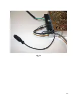
Страница 17: ...17 Fig 17 ...
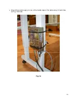
Страница 18: ...18 Mount the power supply on one of the middle legs of the table using 14 wire ties as Fig 18 shows Fig 18 ...
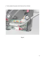
Страница 19: ...19 Tie the cables to the posts on both motors as Fig 19 shows Fig 19 ...
Страница 22: ...22 COPY THE LOGS AND POST THE logs tar gz FILE TO THE SUPPORT PAGE OF www intelliquilter com ...

