background image

Intel® Server System M50CYP2UR Family System Integration and Service Guide


109 

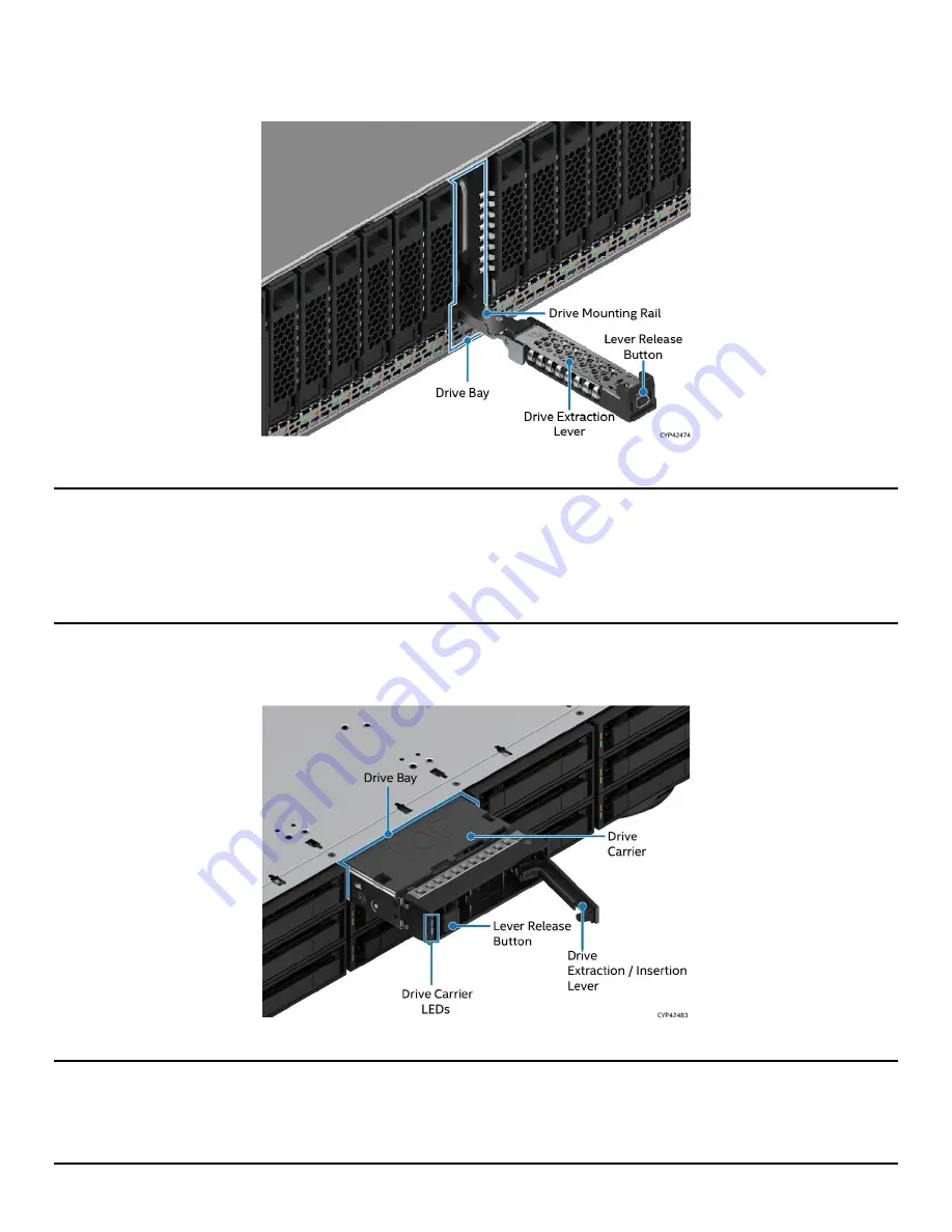
2.5” Drive Bays


The following figure identifies the 2.5” drive bay components.


Figure 140. 

2.5” Drive 

Bay Components 

Note:

 To ensure proper system airflow requirements, all front drive bays must be populated with either a 

drive or supplied drive blank. 

Note: 

The 2.5” drive 

rails in the system are not removable. They slide out so that the storage drives can be 

installed or removed in/from them. When sliding out a drive mounting rail from the system, only pull it as 
much as it allows without forcing it. 

3

.5” Drive Bays


The following figure identifies the 3.5” drive bay components.


Figure 141

. 3.5” 

Drive Bay Components 

Note:

 To ensure proper system airflow requirements, all front drive bays must be populated with a drive 

carrier. Drive carriers must be populated with either a drive or supplied drive blank. 

Note: 

The 3.5” drive 

carrier must be completely removed from the chassis to install a drive into the drive 

carrier.  

Содержание M50CYP2UR Series

Страница 1: ...ration and Service Guide A guide providing instructions for the insertion and extraction of system components and available Intel accessories and spares Rev 1 0 May 2021 Delivering Breakthrough Data C...

Страница 2: ...2 This page intentionally left blank...

Страница 3: ...Intel Server System M50CYP2UR Family System Integration and Service Guide 3 Document Revision History Date Revision Changes May 2021 1 0 Initial production release...

Страница 4: ...gn defects or errors known as errata which may cause the product to deviate from published specifications Current characterized errata are available on request Intel disclaims all express and implied...

Страница 5: ...e when using needle nosed pliers to remove or install a jumper grip the narrow sides of the jumper with the pliers never the wide sides Gripping the wide sides can damage the contacts inside the jumpe...

Страница 6: ...er user notices in the product user guide and specification documents may result in loss of or access to data Weight of the system Due to the weight of a system Intel recommends carrying the system wi...

Страница 7: ...Kit Integration and Service 36 3 1 System Cover Removal Installation 37 3 1 1 System Cover Removal 37 3 1 2 System Cover Installation 38 3 2 Air Duct Removal Installation 39 3 2 1 Air Duct Removal 40...

Страница 8: ...ion 71 3 10 2 Intel VROC 7 5 VMD NVMe RAID Key Removal 72 3 11 Intel SAS Interposer Card and SAS RAID Module Installation Removal 72 3 11 1 Intel SAS Interposer Card Installation 73 3 11 2 Intel SAS I...

Страница 9: ...Carrier 114 6 8 7 3 5 Drive Carrier Installation 116 6 9 Backplane Replacement 117 6 9 1 8 x 2 5 Backplane 117 6 9 2 12 x 3 5 Backplane Installation 119 6 9 3 8 x 2 5 Backplane and 12 x 3 5 Backplane...

Страница 10: ...ng the Processor Heat Sink Anti tilt Wires to the Outward Position 29 Figure 18 Pin 1 Indicator of Processor Carrier Clip 30 Figure 19 Socket Protective Cover Removal 30 Figure 20 PHM Alignment with S...

Страница 11: ...Mount SSD to Bracket 54 Figure 56 3 5 Drive Carrier to 2 5 SSD Bracket Mount Bracket Assembly to Carrier 55 Figure 57 3 5 Drive Carrier to 2 5 SSD Bracket Secure SSD to Carrier 55 Figure 58 3 5 Drive...

Страница 12: ...Figure 100 Front Control Panel Features 84 Figure 101 Front I O Features 85 Figure 102 2 5 Hot Swap Drive Slot LED Identification 85 Figure 103 3 5 Drive Slot LED Identification 85 Figure 104 Intel Se...

Страница 13: ...re 140 2 5 Drive Bay Components 109 Figure 141 3 5 Drive Bay Components 109 Figure 142 Drive Removal 110 Figure 143 Separating Top and Bottom Parts of Drive Blank 110 Figure 144 Attaching the Drive Bl...

Страница 14: ...Me Drive Status LED States 86 Table 4 Drive Activity LED States 86 Table 5 Intel Optane DC Persistent Memory 200 Series Module Support Guidelines 128 Table 6 Standard DRAM DIMMs Compatible with Intel...

Страница 15: ...es Previous generation Intel Xeon processor and Intel Xeon Scalable processor families are not supported The system provides high memory bandwidth and capacity of up to 32 DDR4 DIMMs for memory intens...

Страница 16: ...Software Update and Configuration A short overview describing the system software stack installed on new Intel servers and where to get the latest revisions System Service Chapter 5 System Service Sy...

Страница 17: ...are External Product Specification EPS For the Intel Server Board D50TNP and M50CYP Families Intel Confidential For BIOS setup information on Intel Server M50CYP Family BIOS Setup Utility User Guide F...

Страница 18: ...mware Update Utility SYSFWUPDT Various operating system support Intel System Firmware Update Utility User Guide To obtain full system information Intel SYSINFO Utility for Intel Server M50CYP Family P...

Страница 19: ...Intel server system came pre installed with all the components listed above then skip this chapter and go to Chapter 3 for installation procedures associated with all other system options and accessor...

Страница 20: ...tem and one over the back half of the system To maintain system thermals both top cover panels must always be in place when the system is operational Required Tools and Supplies Anti static wrist stra...

Страница 21: ...panel from the chassis Note A non skid surface or a stop behind the server system may be needed to prevent the server system from sliding on the work surface Figure 3 System Top Cover Removal For each...

Страница 22: ...Air Duct Removal Installation Required Tools and Supplies Anti static wrist strap and conductive workbench pad recommended The Intel Server System M50CYP2U family has three types of air ducts The typ...

Страница 23: ...ght Figure 6 Standard Air Duct for Processor Heat Sink with 1U Height Figure 7 GPGPU Air Duct for Processor Heat Sink with 1U Height For more information about the processor heat sink and compatible a...

Страница 24: ...e fan cage see Letter A 3 Lift the back edge of the air duct to separate the alignment pins on the chassis from the holes on the back corners of the air duct see Letter B 4 Lift the air duct straight...

Страница 25: ...of the air duct until it touches the fan cage Letter B 4 Ensure the alignment pins on the front edge of the air duct align and go into the holes on the top of the fan cage 2 3 2 1 GPGPU Air Duct Brac...

Страница 26: ...the Intel Server System M50CYP2UR family Standard 2U heat sink and standard 1U heat sink The type of heat sink used depends on the system configuration and its thermal requirements Server systems usin...

Страница 27: ...the order specified These instructions assume that all the PHM components are new and the Thermal Interface Material TIM is already applied to the bottom of the heat sink 2 4 1 Processor Heat Sink Mo...

Страница 28: ...processor carrier clip on top of the processor while it is still on the tray 2 Ensure the pin 1 indicator on the processor carrier clip is aligned with the pin 1 indicator of the processor Figure 15...

Страница 29: ...ing To avoid damage to the heat sink grasp it by its narrower top and bottom edges Figure 17 Setting the Processor Heat Sink Anti tilt Wires to the Outward Position 5 Set the anti tilt wires to the ou...

Страница 30: ...to place 10 Ensure all four heat sink corners are securely latched to the carrier clip tabs 2 4 2 Processor Installation Caution Do not touch the socket pins The pins inside the processor socket are e...

Страница 31: ...M Alignment with Socket Assembly 3 Align the pin 1 indicators of the processor carrier clip and processor with the pin 1 indicator on the bolster plate Caution Processor socket pins are delicate and b...

Страница 32: ...lly carefully lower it on to the bolster plate s alignment pins see Letter B 6 Set all four anti tilt wires on the heat sink to the outward position see Letter C Figure 22 Tighten Heat Sink Fasteners...

Страница 33: ...e for standard DDR4 DIMMs and Intel Optane DC persistent memory 200 series modules DDR4 DIMM and Intel Optane PMem will be commonly referred to as Memory module in the following instructions Note See...

Страница 34: ...he device by its outer edges 4 Align the notch at the bottom edge of the Memory module with the key in the DIMM slot see Letter B 5 Insert the Memory module into the slot see Letter C push down on the...

Страница 35: ...e insert from the power supply bay see Letter A 2 Slide the power supply into the power supply bay until it clicks and locks in place see Letter B Note A single power supply configuration requires tha...

Страница 36: ...mponents review all the safety and ESD precautions found in the Safety Warnings section at the beginning of this document System Reference In the following procedures all references to left right fron...

Страница 37: ...al Removal of both top cover panels is necessary when installing or replacing any system component within the server chassis Before removing the top cover power down the system and unplug all peripher...

Страница 38: ...ee Letter B 2 Carefully lift the top cover panel up and away from the chassis Note Each top cover panel can slide along the chassis base for 10 mm and then needs to be lifted 3 1 2 System Cover Instal...

Страница 39: ...k and add in cards installed in the system Standard air duct for processor heat sink with 2U height Standard air duct for processor heat sink with 1U height General Purpose Graphics Processing Unit GP...

Страница 40: ...n 3 2 1 Air Duct Removal The steps for air duct removal are the same for all types of air ducts For the GPGPU air duct see the following subsection before following these steps Figure 32 Air Duct Remo...

Страница 41: ...acket from the top part of the GPGPU air duct see Letter B 3 2 2 Air Duct Installation Figure 34 Air Duct Installation 1 Ensure that all cables are clear of the air duct keep out area on the base of t...

Страница 42: ...onfigured with a GPGPU airduct Once the GPGPU air duct is installed the bracket is installed on top of it Figure 35 GPGPU Air Duct Bracket Installation 1 Insert bracket on top of the GPGPU air duct Pu...

Страница 43: ...x16 mechanical one FH HL single width slot x8 electrical x8 mechanical iPC CYP2URISER1STD NVMe riser card supporting one HL or FL single width slot x16 electrical x16 mechanical two x8 PCIe NVMe Slim...

Страница 44: ...ser Card on Riser Slot 3 Two Views Required Tools and Supplies Anti static wrist strap and conductive workbench pad recommended Phillips head screwdriver 1 For more information about the riser card op...

Страница 45: ...tion 3 2 1 4 If present disconnect all cables internal or external that may be attached to the riser assembly 5 Loosen the two screw mounts on the side of the riser card bracket from the server board...

Страница 46: ...with the blue lines in the figure 2 Using the fastener screws secure the riser card to the riser card bracket Tighten to 5 in lb 3 3 3 PCIe Add in Card Installation All add in cards connected to the...

Страница 47: ...in Section 3 3 1 2 Remove the fastener screw see Letter A and remove the filler panel from the add in card slot see Letter B 3 Insert the add in card until it is fully seated inside the PCIe slot on t...

Страница 48: ...n card that are required See your add in card documentation for additional information 9 Reinstall the air duct see Section 3 2 2 10 Reinstall the system top cover see Section 3 1 2 3 4 Drive Removal...

Страница 49: ...te The 2 5 drive mounting rail does not go all the way out Only pull it as much as it allows without forcing it 3 5 Drive Bays The following figure identifies the 3 5 drive bay components Figure 45 3...

Страница 50: ...upplied blank part to a 7 mm thick SSD Figure 46 Separating Top and Bottom Parts of Drive Blank 1 Remove the drive blank from the system see Section 3 4 3 2 Press the handles at the bottom part of the...

Страница 51: ...stem M50CYP2UR Family System Integration and Service Guide 51 3 4 2 2 5 SSD Drive Installation Figure 48 2 5 7 mm Drive Outside Chassis Ready for Installation Figure 49 2 5 7 mm Drive Installation int...

Страница 52: ...1 Ensure the lever is in the open position and the drive mounting rail is pulled halfway out 2 Align the drive assembly with the open drive bay 3 Insert the assembled 7 mm thick drive or non assembled...

Страница 53: ...ton on the drive extraction lever to release it see Letter A 2 Using the lever pull the drive mounting rail halfway out of the drive bay see Letter B 3 Remove the drive or drive blank from the drive m...

Страница 54: ...degraded performance and reliability concerns the use of the 3 5 drive blank as a 2 5 drive bracket is intended to support SSD type storage devices only Installing a 2 5 hard disk drive into the 3 5...

Страница 55: ...ft side of the drive bracket over the mounting tabs on the drive carrier side rail see Letter E 5 Lower the other side of the drive into the carrier and press down until all mounting tabs lock in plac...

Страница 56: ...2 With the lever in the open position insert the drive assembly into the drive bay see Letter A 3 Push forward until the drive contacts with the backplane 4 Complete the drive installation by closing...

Страница 57: ...mechanism refers to the mechanism required to install remove the OCP adapter Instructions for OCP adapter installation and removal for all three configurations are provided in the following subsection...

Страница 58: ...of the filler first and move the filler slightly to the right ensuring the left end of the filler is out of the slot 3 Pull the filler away from the system see Letter B Figure 61 OCP Adapter Bay Fill...

Страница 59: ...ay slot and push forward until the connectors make secure contact see Letter A 2 Tighten the thumb screw on the right side of the OCP adapter see Letter B 3 5 3 OCP Adapter with Pull Tab Removal Figur...

Страница 60: ...until the right side of the latch contacts the rear panel see Letter A 3 Rotate the latch towards the inside to get the OCP adapter engaged with the connectors and close the latch see Letter B 3 5 5 O...

Страница 61: ...lock to indicate its orientation The following figure shows the features of the lock Figure 66 Internal Lock with Unlock and Lock Orientation Figure 67 OCP Adapter with Internal Lock Installation 1 Po...

Страница 62: ...ernal lock and pull it out see Letter A 4 Install it back in the chassis in reverse orientation see Letter B 5 Push the OCP adapter out of the bay from inside the chassis see Letter C 6 Reinstall the...

Страница 63: ...Slot 1 see Section 3 3 1 5 Locate the M 2 Port 0 connector as shown above 6 Align the notch within the SSD edge connector with the key in the server board M 2 connector and insert the SSD into the co...

Страница 64: ...e air duct see Section 3 2 2 11 Reinstall the system top cover see Section 3 1 2 3 7 Internal Fixed Mount SATA SSD Installation Removal Required Tools and Supplies Anti static wrist strap and conducti...

Страница 65: ...Intel Server System M50CYP2UR Family System Integration and Service Guide 65 Figure 72 Peripheral Power Connector Identification Figure 73 SATA Ports on Server Board...

Страница 66: ...age 5 Mount a 2 5 SSD to the drive bracket see Letter A 6 Using four 4 screws in the accessory kit secure the SSD to the drive bracket see Letter B Tighten to 8 in lb 7 Repeat steps 4 and 6 if install...

Страница 67: ...let 1 Power off the system and disconnect the power cable s 2 Remove the system top cover see Section 3 1 1 3 Remove the air duct see Section 3 2 1 4 Detach the SATA and power cables from the SSD Figu...

Страница 68: ...on and removal of a midplane card The steps in this section apply to midplane card installation and removal on either of the two positions in the system 3 8 1 Midplane Card Installation Figure 78 Midp...

Страница 69: ...cable s 2 Remove the system top cover see Section 3 1 1 3 Remove the air duct see Section 3 2 1 4 Disconnect all the connectors attached to the midplane card 5 Unscrew the four 4 screws on the midplan...

Страница 70: ...tform Module TPM Installation 1 Power off the system and disconnect the power cable s 2 Remove the system top cover see Section 3 1 1 3 Remove the air duct see Section 3 2 1 4 Locate the TPM module co...

Страница 71: ...r to the Intel Server System M50CYP2UR Family Technical Product Specification 3 10 1 Intel VROC 7 5 VMD NVMe RAID Key Installation Figure 81 Intel VROC Key Insertion 1 Power off the system and disconn...

Страница 72: ...nector 5 Reinstall the air duct see Section 3 2 2 6 Reinstall the system top cover see Section 3 1 2 3 11 Intel SAS Interposer Card and SAS RAID Module Installation Removal This section provides instr...

Страница 73: ...1 3 Remove the air duct see Section 3 2 1 4 Align the four 4 screw holes of the SAS interposer card with the matching threaded holes on the base of the chassis see Letter A 5 Secure the SAS interposer...

Страница 74: ...ver see Section 3 1 1 3 Remove the air duct see Section 3 2 1 4 If an installed RAID module needs to be removed see Section 3 11 4 5 Disconnect all the connectors attached to the SAS interposer card 6...

Страница 75: ...the SAS RAID module from its packaging 5 Insert the four 4 plastic barrel standoffs into the matching holes in the SAS interposer card see Letter A 6 Align the SAS RAID module mounting holes over the...

Страница 76: ...es connected to the SAS RAID module 5 Remove the four locking pins from each standoff see Letter A 6 Grasp the SAS RAID module on both sides and lift firmly until the connector is disengaged from the...

Страница 77: ...ily Configuration Guide for available options Required Tools and Supplies Anti static wrist strap and conductive workbench pad recommended Phillips head screwdriver 1 3 12 1 Intel SAS Expander Card In...

Страница 78: ...Reinstall the air duct see Section 3 2 2 9 Reinstall the system top cover see Section 3 1 2 3 13 Intel RAID Maintenance Free Backup Unit RMFBU and Mounting Bracket Installation Removal This section p...

Страница 79: ...h holder slightly up see Letter B and insert the notch into opening until it clicks see Letter C 3 Bring the latch down until it is aligned vertically see Letter D Figure 90 Insert Super Cap Battery 4...

Страница 80: ...le s 2 Remove the system top cover see Section 3 1 1 3 Remove the air duct see Section 3 2 1 4 Remove the cable clip if installed by unfastening the two screws holding the clip to the chassis 5 Align...

Страница 81: ...isconnect the RMBFU cable from the RAID module it is attached to 4 Lift the latch up slightly to unlock the RMFBU assembly from the mounting bracket see Letter A 5 Slide the RMFBU assembly see Letter...

Страница 82: ...intel com To ensure that the embedded platform management subsystem is configured properly the latest FRU and SDR data for each compute module must be installed after updating the full system software...

Страница 83: ...rvice personnel a reference to identify and locate the features associated with the Intel Server System M50CYP2UR family 5 1 Front Drive Bay Options Figure 95 8 x 2 5 Front Drive Bay Configuration Fig...

Страница 84: ...ver System M50CYP2UR Family System Integration and Service Guide 84 5 2 Back Panel Front Control Panel Front I O Features Figure 99 Back Panel Features Figure 100 Front Control Panel Features OCP Adap...

Страница 85: ...5 3 Drive Tray LED Identification The following figures show 2 5 and 3 5 drive bays Two LEDs for each drive bay are Amber Status LED and Green Activity LED The following tables list the different LED...

Страница 86: ...drive activity SAS NVMe LED stays on SATA LED stays off Power on with drive activity SAS NVMe LED blinks off when processing a command SATA LED blinks on when processing a command Power on and drive s...

Страница 87: ...ice Guide 87 5 4 Server Board Features The following figure provides a general overview of the physical server board identifying key feature and component locations Figure 104 Intel Server Board M50CY...

Страница 88: ...es LEDs to identify system status and or indicate a component fault The following figures identify the diagnostic LEDs and their location on the server board Figure 105 Intel Light Guided Diagnostics...

Страница 89: ...server board includes several jumper blocks that can be used to configure protect or recover specific features of the server board The following figure identifies the location of each jumper block on...

Страница 90: ...ecautions found in the Safety Warnings section at the beginning of this document System Reference In the following procedures all references to left right front top and bottom assume the reader is fac...

Страница 91: ...r screws one on each side of the front cover and one on each side of the back cover need to be removed to detach each top cover panel from the chassis Note A non skid surface or a stop behind the serv...

Страница 92: ...2 Air Duct Removal Installation Required Tools and Supplies Anti static wrist strap and conductive workbench pad recommended The Intel Server System M50CYP2U family has three types of air ducts The ty...

Страница 93: ...ht Figure 113 Standard Air Duct for Processor Heat Sink with 1U Height Figure 114 GPGPU Air Duct for Processor Heat Sink with 1U Height For more information about the processor heat sink and compatibl...

Страница 94: ...ins from the fan cage 3 Lift the back edge of the air duct to separate the alignment pins on the chassis from the holes on the back corners of the air duct 4 Lift the air duct straight up and remove i...

Страница 95: ...dge of the air duct until it touches the fan cage 4 Ensure the alignment pins on the front edge of the air duct align and go into the holes on the top of the fan cage 6 2 2 1 GPGPU Air Duct Bracket In...

Страница 96: ...can also be replaced without removing the entire system fan assembly See Section 6 4 for replacing individual fans Figure 119 System Fan Assembly Removal 1 Ensure the system power is off and disconne...

Страница 97: ...fan module see Letter B Align the two guide pins on each side of the fan module with the latch receivers on each chassis sidewall 10 Push down on both ends of the fan module until fully seated Figure...

Страница 98: ...thin the system while swapping out a defective system fan Figure 122 Individual Fan Removal or Installation To remove a failed individual fan 1 Remove the system top cover see Section 6 1 1 2 Remove t...

Страница 99: ...be commonly referred to as Memory module in the following instructions Note See Appendix C for general memory population rules Figure 123 Memory Module Removal 1 Ensure the system power is off and dis...

Страница 100: ...C push down on the Memory module until the ejection tabs snap into place see Letter D 13 Ensure that the ejection tabs are firmly in place see Letter E 14 Reinstall the air duct see Section 6 2 2 15 R...

Страница 101: ...Supply Installation 4 If present remove the insert from the power supply bay see Letter A 5 Slide the power supply into the power supply bay until it clicks and locks in place see Letter B 6 7 Process...

Страница 102: ...all four anti tilt wires on the heat sink to the inward position see Letter C 7 Lift the PHM straight up off the server board see Letter D 8 After removing the PHM visually inspect that the socket is...

Страница 103: ...b on each corner of the processor carrier clip and lift the clip up to remove the processor carrier clip from the heat sink see Letter D 6 7 2 PHM and Processor Installation To properly assemble the P...

Страница 104: ...clip on top of the processor while it is still on the tray 2 Ensure the pin 1 indicator on the processor carrier clip is aligned with the pin 1 indicator of the processor Figure 132 Installing Proces...

Страница 105: ...packaging To avoid damage to the heat sink grasp it by its narrower top and bottom edges Figure 134 Processor Heat Sink Anti tilt Wires in the Outward Position 5 Set the anti tilt wires to the outward...

Страница 106: ...nto place 10 Ensure all four heat sink corners are securely latched to the carrier clip tabs 6 7 2 2 Processor Installation Caution Do not touch the socket pins The pins inside the processor socket ar...

Страница 107: ...cessor socket pins are delicate and bend easily Use extreme care when placing the PHM onto the processor socket Do not drop it Figure 138 PHM Installation onto Server Board 4 Set all four anti tilt wi...

Страница 108: ...7 mm thick SSDs with a form factor of 2 5 are supported when used in conjunction with the supplied drive blank for 2 5 bays Each storage drive that interfaces with a backplane is mounted to a tool les...

Страница 109: ...out so that the storage drives can be installed or removed in from them When sliding out a drive mounting rail from the system only pull it as much as it allows without forcing it 3 5 Drive Bays The f...

Страница 110: ...mm Drives The Intel Server System M50CYP2UR family supports 2 5 SSDs with 7 mm of thickness when used in conjunction with the supplied blanks The supplied blank for 2 5 bays has two parts top and bot...

Страница 111: ...5 7 mm SSD drive into the top part of the drive blank as shown in the above figure Note Inserting it in the opposite direction could potentially scratch the gold fingers of the SSD connector 6 8 3 2...

Страница 112: ...ting rail is pulled halfway out 2 Align the drive assembly with the open drive bay 3 Insert the assembled 7 mm thick drive or non assembled 15 mm thick drive into the drive bay see Letter A Note Intel...

Страница 113: ...r pull the carrier from the drive bay all the way out see Letter B 6 8 5 3 5 HDD Drive Assembly Drive Blank Removal Drive Removal Figure 150 3 5 Drive Assembly Drive Blank Drive Removal 1 Hold the dri...

Страница 114: ...ount a 2 5 SSD Note Due to degraded performance and reliability concerns the use of the 3 5 drive blank as a 2 5 drive bracket is intended to support SSD type storage devices only Installing a 2 5 har...

Страница 115: ...position the mounting holes on the left side of the drive bracket over the mounting tabs on the drive carrier side rail see Letter E 6 Lower the other side of the drive into the carrier and press down...

Страница 116: ...1 Align the drive assembly drive and drive carrier with the open drive bay 2 With the lever in the open position insert the drive assembly into the drive bay see Letter A and push forward until the d...

Страница 117: ...ed Tools and Supplies Anti static wrist strap and conductive workbench pad recommended Phillips head screwdriver 1 Figure 156 8 x 2 5 Backplane Removal 1 Power off the system and remove power cable s...

Страница 118: ...any components on the backplane 10 Align and secure the holes in the backplane to the guide pins on the chassis as shown by the orange lines 11 Slide the backplane down to lock it into place see Lette...

Страница 119: ...ackplane Removal 1 Power off the system and remove the power cable s 2 Remove the system top cover see Section 6 1 1 3 Remove the air duct see Section 6 2 1 4 Remove all drives and drive blanks from t...

Страница 120: ...e must have PCIe signals cabled to the appropriate backplane SlimSAS connector from any of the following PCIe signal sources Available server board x4 PCIe SlimSAS connectors Optional tri mode RAID ad...

Страница 121: ...more cables are to be installed reinstall the system fan assembly See Section 6 3 6 10 System Battery Replacement Required Tools and Supplies Anti static wrist strap and conductive workbench pad reco...

Страница 122: ...in cards and I O modules 8 Remove riser card assemblies see Section 3 3 1 9 Remove all options installed onto the server board including if installed TPM Module M 2 SSD Internal mounted U 2 SSD Intel...

Страница 123: ...doffs see Letter A 20 Fasten the server board to the chassis using all the screws see Letter B Tighten to 5 in lb 21 Re attach all cables previously removed from the server board 22 Install processor...

Страница 124: ...ive using one of the support phone numbers available at https www intel com content www us en support contact support html charges may apply Intel also offers Partner Alliance Program members around t...

Страница 125: ...s cable routing channels along each chassis sidewall Cables should not be routed directly in front of the system fans Cables should not be routed through the center of the server board between the mem...

Страница 126: ...when installing DDR4 DIMMs Mixing rules o Mixing DDR4 DIMMs of different frequencies and latencies is not supported within or across processors If a mixed configuration is encountered the BIOS attempt...

Страница 127: ...ore memory slots on other IMCs For multiple DIMMs per channel o Only one Intel Optane persistent memory 200 series module is supported per memory channel o Intel Optane persistent memory 200 series mo...

Страница 128: ...6 2400 Table 6 Standard DRAM DIMMs Compatible with Intel Optane Persistent Memory 200 Series Module Type Ranks per DIMM and Data Width DIMM Size GB 8 Gb DRAM density 16 Gb DRAM density RDIMM PTH up to...

Страница 129: ...ating in a degraded state although still functioning or system is operating in a redundant state but with an impending failure warning Redundancy loss such as power supply or fan Applies only if the a...

Страница 130: ...recoverable system is halted Fatal alarm system has failed or shut down Processor CATERR signal asserted MSID mismatch detected CATERR also asserts for this case CPU 0 is missing Processor Thermal Tr...

Страница 131: ...dentify the last POST routine that was run before the error occurred helping to isolate the possible cause of the hang condition Each POST code is represented by eight LEDs four green LEDs and four am...

Страница 132: ...are displayed to the diagnostic LEDs that show the execution point in the MRC operational path at each step Table 9 MRC Progress Codes Post Code Hex Upper Nibble Lower Nibble Description 8h 4h 2h 1h...

Страница 133: ...memory failure beep code of three long beeps as identified in Table 10 Table 10 MRC Fatal Error Codes Post Code Hex Upper Nibble Lower Nibble Description 8h 4h 2h 1h 8h 4h 2h 1h E8 1 1 1 0 1 0 0 0 No...

Страница 134: ...SAD setting AA 1 0 1 0 1 0 1 0 Protocol layer and other uncore settings AB 1 0 1 0 1 0 1 1 Transition links to full speed operation AE 1 0 1 0 1 1 1 0 Coherency settings AF 1 0 1 0 1 1 1 1 KTI initial...

Страница 135: ...mbling CA 1 1 0 0 1 0 1 0 Internal Use CB 1 1 0 0 1 0 1 1 Check RAS support CC 1 1 0 0 1 1 0 0 Pmem ADR Init CD 1 1 0 0 1 1 0 1 Internal Use CE 1 1 0 0 1 1 1 0 Memory Late Init CF 1 1 0 0 1 1 1 1 Dete...

Страница 136: ...E SCSI begin A6 1 0 1 0 0 1 1 0 DXE SCSI reset A7 1 0 1 0 0 1 1 1 DXE SCSI detect A8 1 0 1 0 1 0 0 0 DXE SCSI enable AB 1 0 1 0 1 0 1 1 DXE SETUP start AC 1 0 1 0 1 1 0 0 DXE SETUP input wait AD 1 0 1...

Страница 137: ...the SEL The system continues booting in a degraded state The user may want to replace the erroneous unit The POST Error Pause option setting in the BIOS Setup does not affect this error Major An error...

Страница 138: ...abled Major 8131 CPU 1 disabled Major 8160 CPU 0 unable to apply microcode update Major 8161 CPU 1 unable to apply microcode update Major 8170 CPU 0 failed Self Test BIST Major 8171 CPU 1 failed Self...

Страница 139: ...IMM Major 8536 Memory failed test initialization CPU0_DIMM_H2 Remove the disabled DIMM Major 8537 Memory failed test initialization CPU0_DIMM_H3 Remove the disabled DIMM Major 8538 Memory failed test...

Страница 140: ...he disabled DIMM Major 8560 Memory encountered a Serial Presence Detection SPD failure CPU0_DIMM_A1 Major 8561 Memory encountered a Serial Presence Detection SPD failure CPU0_DIMM_A2 Major 8562 Memory...

Страница 141: ...1 Major 857F Go to 85E0 Memory encountered a Serial Presence Detection SPD failure CPU1_DIMM_C2 Major 85C0 Memory failed test initialization CPU1_DIMM_C3 Remove the disabled DIMM Major 85C1 Memory fai...

Страница 142: ...ion SPD failure CPU1_DIMM_D1 Major 85E2 Memory encountered a Serial Presence Detection SPD failure CPU1_DIMM_D2 Major 85E3 Memory encountered a Serial Presence Detection SPD failure CPU1_DIMM_D3 Major...

Страница 143: ...o the memory was detected 3 long and 1 short CPU mismatch error E5 E6 System halted because a fatal error related to the CPU family core cache mismatch was detected The integrated BMC may generate bee...

Страница 144: ...d to the SEL If the BIOS Setup option Post Error Pause is enabled operator intervention is required to continue booting the system If the BIOS Setup option POST Error Pause is disabled the system cont...

Страница 145: ...to highest common frequency Does not generate an error this is not an error condition Continues to boot the system successfully If the link frequencies for all Intel UPI links cannot be adjusted to b...

Страница 146: ...ystem When reused all of the original packaging material must be used including both boxes and each inner packaging component In addition all inner packaging components MUST be reinstalled in the prop...

Страница 147: ...per insert iPN K66526 001 on the bottom left foam See the following figure 3 Pack the server system with red EPE sheet iPN K58342 001 See the following figure 4 Pack the system wrapped with EPE sheet...

Страница 148: ...5 Place the accessory kit box iPN H49469 001 in the center foam cushion Place the extension rails in the two narrow foam cavities See the following figure 6 Close the inner box 7 Close the outer box...

Страница 149: ...m plugs into shall be installed near the equipment and shall be easily accessible SAFETY STEPS Whenever you remove the chassis covers to access the inside of the system follow these steps 1 Turn off a...

Страница 150: ...and chassis parts Contact should be made with care Consider wearing protective gloves Danger of explosion if the battery is incorrectly replaced Replace only with the same or equivalent type recommend...

Страница 151: ...le bo tier pour acc der l int rieur du syst me suivez les consignes suivantes 1 Mettez hors tension tous les p riph riques connect s au syst me 2 Mettez le syst me hors tension en mettant l interrupte...

Страница 152: ...nt attention aux broches aigu s des cartes et aux bords tranchants du capot Nous vous recommandons l usage de gants de protection Danger d explosion si la batterie n est pas remont e correctement Remp...

Страница 153: ...eabdeckung abnehmen um an das Systeminnere zu gelangen sollten Sie folgende Schritte beachten 1 Schalten Sie alle an Ihr System angeschlossenen Peripherieger te aus 2 Schalten Sie das System mit dem H...

Страница 154: ...d Geh useteile scharfe Spitzen und Kanten aufweisen Arbeiten an Platinen und Geh use sollten vorsichtig ausgef hrt werden Sie sollten Schutzhandschuhe tragen Bei falschem Einsetzen einer neuen Batteri...

Страница 155: ...el telaio per accedere all interno del sistema seguire i seguenti passi 1 Spegnere tutti i dispositivi periferici collegati al sistema 2 Spegnere il sistema usando il pulsante spento acceso dell inter...

Страница 156: ...ere surriscaldati Fare attenzione alla presenza di piedini appuntiti e parti taglienti sulle schede e sul telaio consigliabile l uso di guanti di protezione Esiste il pericolo di un esplosione se la p...

Страница 157: ...DAD Cuando extraiga la tapa del chasis para acceder al interior del sistema siga las siguientes instrucciones 1 Apague todos los dispositivos perif ricos conectados al sistema 2 Apague el sistema pres...

Страница 158: ...n conviene tener en cuenta que en el chasis o en el tablero puede haber piezas cortantes o punzantes Por ello se recomienda precauci n y el uso de guantes protectores Existe peligro de explosi n si l...

Страница 159: ...Intel Server System M50CYP2UR Family System Integration and Service Guide 159 1 2 3 4 5 ESD 6 1 2 3...

Страница 160: ...Intel Server System M50CYP2UR Family System Integration and Service Guide 160 1 2 3 4 5...

Страница 161: ...raphical User Interface I2 C Inter integrated Circuit bus IMC Integrated Memory Controller iPC Intel Product Code IPMI Intelligent Platform Management Interface ISTA International Safe Transit Associa...

Страница 162: ...Registered DIMM RMFBU RAID Maintenance Free Backup Unit ROC RAID On Chip SAS Serial Attached SCSI SATA Serial Advanced Technology Attachment SEL System Event Log SCA Single Connector Attachment SCSI S...

Отзывы: