Intel® Server System M50CYP2UR Family System Integration and Service Guide
114
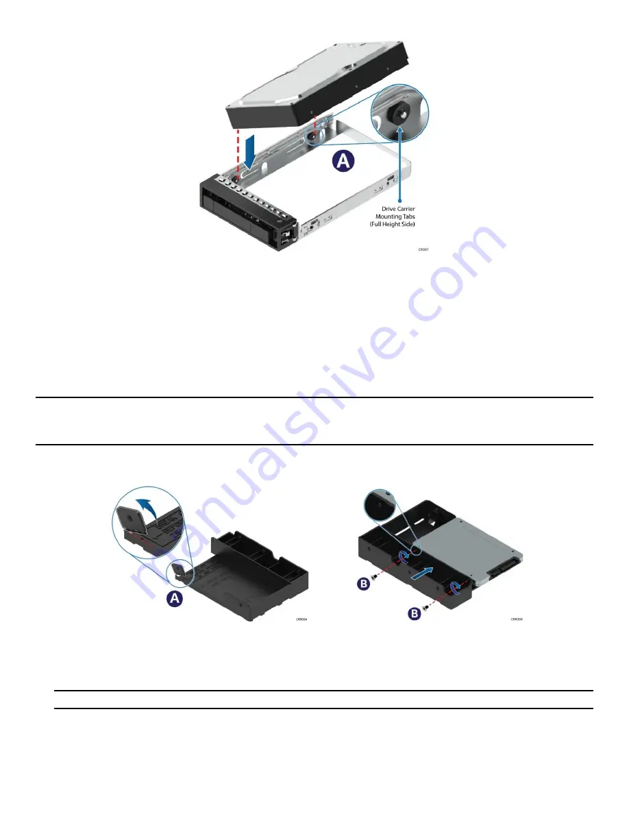
Figure 151. 3.5
” D
rive Assembly
–
Drive Installation to Carrier
3.
Position the rear drive connector towards the back of the drive carrier.
4.
Align and position the mounting holes on the left side of the drive over the mounting tabs on the drive
carrier side rail (see Letter A).
5.
Lower the other side of the drive into the carrier and press down until all mounting tabs lock in place.
6.8.6
Assembly of
2.5”
SSD Drive
into a 3.5” Drive
Carrier
The 3.5” drive blank can also be used
to mount a 2.5” SSD.
Note:
Due to degraded performance and reliability concerns, the use of the 3.5” drive blank as a 2.5” drive
bracket is intended to support SSD type storage devices only.
Installing a 2.5” hard disk drive into the 3.5”
drive blank is not supported.
1.
Remove the drive blank from the drive carrier. See steps 1 and 2 of
Section 6.8.4
Figure 152. 3.5" Drive Carrier
to 2.5” SSD
Bracket
–
Tab Removal and Mount SSD to Bracket
2.
Break off the small side tab from the side of the drive blank, making the drive blank into a
2.5” drive
bracket (see Letter A).
Note:
Once the side tab is removed, it cannot be re-attached to the drive blank.
3.
Mount and secure a 2.5” SSD to the drive bracket using two screws at the locations shown above
(see Letter B). Tighten to 8 in-lb.


