background image

10


Innovative Circuit Technology Ltd.


WEB-BASED CONFIGURATION UTILITY 

These panels are equipped with a built-in web server to enable full remote 
monitoring and control using any standard web browser, such as Microsoft Edge, 
Google Chrome, or Mozilla Firefox. To connect with your networked panel, do 
the following: 
 

1.


Start Your Browser. 

2.


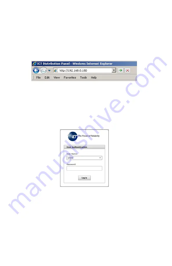
Enter the IP address of the panel in the address field of your browser as 
shown.  


Figure 4. 


If the panel is connected to a network with a DHCP server, the panel will 
be assigned an IP address automatically. To find the current address of 
your panel check the Network screen, line thre

e, on the unit’s front 

panel LCD display. (see Fig. 4) Otherwise the panel will use the factory 
default IP address of 

192.168.0.180

, as shown above. 

3.


Enter your user name and password. The default Administrator user 
name is 

admin

, and there is no password by default. 


Figure 5. 


Once your browser is connected to the unit, the Status & Control page for the 
panel will be displayed, as shown. See the following section for descriptions on 
how to use the various monitoring, configuration, and control features available 

through the panel’s graphical web interface.


To log out, click on the Logout link on the top right of your browser window. The 
system will also automatically log off the user after 20 minutes of inactivity. 


Содержание Distribution 2 Series

Страница 1: ...Innovative Circuit Technology Ltd Distribution Series 2 Intelligent Distribution Panel with Remote Power Control INSTRUCTION MANUAL 855 313 500 Model ICT180SE 12IRC...

Страница 2: ...ower and allow to cool before removing or replacing Wiring terminals may be HOT to touch Disconnect power and allow to cool before disconnecting load wires Install unit in a restricted access location...

Страница 3: ...FIGURATION UTILITY Error Bookmark not defined Status Control 11 Alarm Status 12 Device Setup 12 Output Setup 14 Network setup 16 E mail Setup 19 Alarm setup 20 User Setup 22 Maintenance 22 MOBILE WEB...

Страница 4: ...splay Fuse status is also displayed by an LED indicator located over each fuse Form C alarm contacts C NO NC are provided on the back of the panel which can be connected to an external alarm circuit f...

Страница 5: ...ntact sensors 5 LAN PORT For remote monitoring via TCP IP network 6 CHASSIS GROUND STUD For Earth ground connection 7 OUTPUT TERMINAL BLOCK 1 9 For DC load connections up to 25A each pair 8 POSITIVE I...

Страница 6: ...sulated stud labeled and the negative of the power source to the black insulated stud labeled 6 Re install plastic shield s to the output terminal block s and plastic caps to the input studs 7 For rem...

Страница 7: ...ve the set value Alarm Input 1 5 Activate Alarm Form C Contact is checked Digital Alarm is triggered Output Over Current Alarm 1 12 Activate Alarm Form C Contact is checked Output Current is above the...

Страница 8: ...3 for screen order Figure 3 LCD Display Screens Holding the Output Select button for 2 seconds at any screens will return you to the main screen Holding the Output Select button for 20 seconds at any...

Страница 9: ...guration utility Line 2 Displays the output status ENABLED for output enabled DISABLED for output disabled and FUSE OPEN for blown or missing fuse Line 3 Displays the output voltage Voltage display wi...

Страница 10: ...ress of your panel check the Network screen line three on the unit s front panel LCD display see Fig 4 Otherwise the panel will use the factory default IP address of 192 168 0 180 as shown above 3 Ent...

Страница 11: ...ive Input Alarms for alarms that have been enabled see Alarm Setup page will be shown on this page A grey Alarm Input indicator box shows that the sensor input is ready a red box indicates that that e...

Страница 12: ...name or IP address of the NTP Server used for date and time synchronization such as pool ntp org Time Zone Select the appropriate time zone relative to GMT for your unit so that the NTP server time c...

Страница 13: ...hdog Enabled Check this box to enable the selected Watchdog Primary IP Address Enter the remote IP address you would like the selected Watchdog to monitor If left blank the unit will monitor the Gatew...

Страница 14: ...ired Output State After Panel Reset Sets the state for the output after an input power failure or soft reset of the panel Select one of the following Restore last State If this option is selected the...

Страница 15: ...ge if the Auto Recovery function is not enabled Auto Recovery Threshold Enter the voltage level at which the selected output will automatically be reconnected This value must be at least 0 5V above th...

Страница 16: ...omatically assign IP addresses Enabled as default setting To manually assign a static IP address to the unit uncheck this box then set the following parameters IP Address Specify a unique IP address f...

Страница 17: ...when an alarm or fault occurs The information available from the SNMP agent is described in a MIB Management Information Base file which can be downloaded from the panels Help page The unique panel M...

Страница 18: ...defaults are well known SNMPv3 Settings User Name Enter the user name for SNMPv3 access Authentication Protocol Select the SNMPv3 authentication protocol None MD5 or SHA Authentication Password If an...

Страница 19: ...rnet Service Provider ISP E mail SMTP Server Enter the name or the IP address of your SMTP server used for sending outgoing e mail e g smtp gmail com SMTP Port Enter the port used by your SMTP server...

Страница 20: ...led due the voltage crossing one of the load shed settings configured on the Output Setup page The Network Watchdog triggers Check this box to receive an e mail notification after the Network Watchdog...

Страница 21: ...er the Over Current alarm Activate Form C Contact Checking this box will cause the Alarm relay to trigger for an over current condition Send E mail Checking this box will cause the unit to send a Syst...

Страница 22: ...ch user requires Administrator This level has full access to the panel settings and can set up users and change passwords admin is the default user Control User has read only access to the panel but c...

Страница 23: ...ile for your model unit from the ICT website ict power com De compress this file then press the Choose File button and link to this file Begin the firmware update by clicking the Update Now button Sen...

Страница 24: ...s enabled on the Device Setup page the outputs will be enabled in sequence instead of enabling them simultaneously Tap the Disable All Outputs button to disable DC power to all outputs PASSWORD RESET...

Страница 25: ...b Enter the HTTP port number that the panel is using in the Start and End fields The default HTTP port for the panel is 80 c Select Both under Protocol TCP and UDP d Enter the local IP address of the...

Страница 26: ...obtain a Static IP address from your ISP it will not change which will ensure more predictable access to the panel from a remote location If a static IP address is not available you can use a Dynamic...

Страница 27: ...r txt bell ca Rogers cellnumber pcs rogers com Telus cellnumber msg telus com Virgin Mobile Can cellnumber vmobile ca TROUBLESHOOTING I am unable to access the web based configuration utility Check th...

Страница 28: ...the Send E mail checkboxes are ticked for any alarm conditions for which you wish to receive e mail notifications Verify your e mail settings by going to the Maintenance page on the panel s web utili...

Страница 29: ...facturers specifications Power Consumption 3 W all outputs enabled Maximum Cable Length 100 meters Voltage Drop without fuse 60mV Typical Alarm Form C Contacts Form C Dry Contacts 1A 60VDC Max Alarm S...

Страница 30: ...td Alarm Connectors Euro Terminal Block M2 Screws 16 28AWG Wire Range 1in lbs Max Operating Temperature 20 C to 60 C Weight 8 0lbs 3 6kg Warranty 2 years Dimensions 19 0 x 9 3 x 1 7 483mm x 236mm x 44...

Страница 31: ...CT website at www ict power com support warranty repair The Purchaser shall at their own risk and cost return the defective product to ICT s factory or designated repair center once an RMA is issued b...

Страница 32: ...sustained temperatures outside the specified operating range of the equipment exposure to power surges and or electrical surges improper grounding mold or dust animal or insect damage water damage or...

Отзывы: