background image

1

Form MHD56087

READ THIS MANUAL BEFORE USING THESE PRODUCTS. This manual
contains important safety, installation, operation and maintenance infor-
mation. Make this manual available to all persons responsible for the
operation, installation and  maintenance of these products.

WARNING

Do not use this winch for lifting, supporting, or transporting people or lifting or supporting
loads over people.

Always operate, inspect and maintain this winch in accordance with American National
Standards Institute Safety Code (ASME B30.7) and any other applicable safety codes and
regulations.

Refer all communications to the nearest Ingersoll-Rand Material Handling Office or
Distributor.

Form MHD56087
Edition 3
April 1997
71146690

©

 1997 Ingersoll-Rand Company

PARTS, OPERATION AND MAINTENANCE MANUAL

THIRD GENERATION

AIR WINCHES

MODEL FA5A

Содержание force5 FA5A-LAK1

Страница 1: ...ting supporting or transporting people or lifting or supporting loads over people Always operate inspect and maintain this winch in accordance with American National Standards Institute Safety Code ASME B30 7 and any other applicable safety codes and regulations Refer all communications to the nearest Ingersoll Rand Material Handling Office or Distributor Form MHD56087 Edition 3 April 1997 7114669...

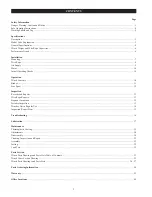
Страница 2: ...ontrols 10 Brakes 11 Free Spool 12 Inspection Records and Reports 13 Wire Rope Reports 13 Frequent Inspection 13 Periodic Inspection 13 Winches Not in Regular Use 14 Inspection Report Form 15 Troubleshooting 16 Lubrication 17 Maintenance Thermoplastic Coating 19 Adjustments 20 Disassembly 20 Cleaning Inspection and Repair 25 Assembly 25 Testing 32 Load Test 32 Parts Section Winch Parts Drawings an...

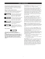
Страница 3: ...n of mechanics common hand tools as well as special Ingersoll Rand or recommended tools 2 Safety procedures precautions and work habits established by accepted industry standards Ingersoll Rand cannot know of or provide all the procedures by which product operations or repairs may be conducted and the hazards and or results of each method If operation or maintenance procedures not specifically rec...

Страница 4: ...c sections in the manual for additional safety information 1 Only allow people trained in safety and operation of this product to operate and maintain this winch 2 Only operate a winch if you are physically fit to do so 3 When a DO NOT OPERATE sign is placed on the winch or controls do not operate the winch until the sign has been removed by designated personnel 4 Before each shift the operator sh...

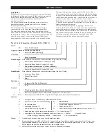
Страница 5: ...c drum band brake fully disengages in both the haul in and payout directions Model Code Explanation Example FA5A LXK1G FA 5 A L X K 1 G Series FA Force 5 Air Powered Capacity Based on wire rope at mid drum 5 5 tons 10 000 lb 4 536 kg Generation A Third Generation Drum Length Note addition of drum brake reduces the drum length 3 inches 76 mm S Short without Drum Brake 15 inches 381 mm S Short with ...

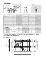
Страница 6: ...20 FA5A SAK1 1 175 534 FA5A SAK2 1 175 534 FA5A SMX1 1 120 509 N A FA5A SAX1 1 165 530 FA5A SAX2 1 165 530 FA5A LXK1 1 251 569 FA5A LXK2 1 263 574 FA5A LMK1 1 363 620 FA5A LMK2 1 380 627 FA5A LAK1 1 390 632 FA5A LAK2 1 390 632 FA5A LMX1 1 333 606 N A FA5A LAX1 1 378 626 FA5A LAX2 1 378 626 Winch Wire Rope Storage Capacities feet metres Drum Length Storage Notes Wire Rope Diameter 5 8 inch 16 mm 3 ...

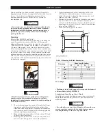
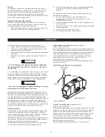
Страница 7: ...must only be mounted by bolting to a suitable foundation Do not attempt to mount the winch by welding to a foundation structure 1 The winch mounting surface must be flat and of sufficient strength to handle the rated load plus the weight of the winch and attached equipment An inadequate foundation may cause distortion or twisting of the winch uprights and side rails resulting in winch damage 2 Mak...

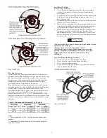
Страница 8: ... Rope Refer to Dwg MHP0652 1 Cut wire rope to length and fuse end to prevent fraying of strands in accordance with the wire rope manufacturer s instructions 2 Feed the end of the wire rope into the wire rope anchor hole in the drum and pull through approximately three feet 1 metre of wire rope 3 Forming a large loop with the wire rope insert the end back into the top of the anchor hole 4 Place the...

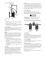
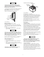
Страница 9: ... the supply lines are also helpful Mufflers optional feature Make sure mufflers are installed in winch exhaust ports and are functioning correctly Dwg MHP0498 Notes 1 Maintain a minimum of 3 tight wraps of wire rope on drum at all times 2 Ensure wire rope does not exceed top layer requirement Refer to SPECIFICATIONS section 3 Maintain minimum of 1 6 feet 0 5 metre per inch of drum length Example f...

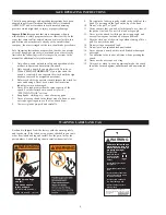
Страница 10: ...ing people Never lift loads over people Operators must be physically competent Operators must have no health condition which might affect their ability to act and they must have good hearing vision and depth perception The winch operator must be carefully instructed in his duties and must understand the operation of the winch including a study of the manufacturer s literature The operator must tho...

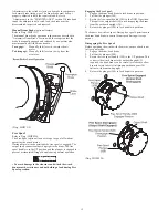
Страница 11: ...acity of the winch When an overload condition is sensed air is directed to the emergency shut off valve to isolate air to the winch If the overload device is activated the load must be reduced Reset the Emergency Stop Valve and operate the winch in the payout direction to lower the load Winch Brakes Automatic Disc Brake The automatic disc brake is a spring applied air released brake When the winch...

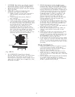
Страница 12: ...ndle is in the UP position and the plunger is engaged to prevent accidental shifting of handle during normal operation WARNING To avoid damage to the structure and winch the winch drum must be stationary and not holding a load during Free Spool operation Engaging the Free Spool 1 Engage the drum band brake to lock drum in position 2 Pull out the plunger 508 3 Rotate the free spool handle 509 to th...

Страница 13: ...ce of malfunction such as abnormal noises 1 WINCH Prior to operation visually inspect winch housings controls brakes sideframes uprights and drum for indications of damage Any discrepancies noted must be reviewed and inspected further by authorized personnel instructed in the operation safety and maintenance of this winch 2 WIRE ROPE Visually inspect all wire rope which can be expected to be in us...

Страница 14: ... Clean and replace components as necessary Adjustments can be made to the drum band brake to compensate for normal brake lining wear Refer to Adjustments in the MAINTENANCE section If brake band cannot be adjusted to hold rated load replace the brake band assembly Adjustments cannot be made to the disc brake The disc brake must be repaired as described in the MAINTENANCE section 7 FOUNDATION or SU...

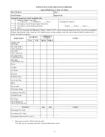
Страница 15: ... Standards and codes of practice If in doubt about an existing condition contact the nearest Ingersoll Rand distributor or the factory for technical assistance COMPONENT CONDITION CORRECTIVE ACTION NOTES Pass Fail Repair Replace Uprights and Sideframes Drum Band Brake 125 Load Test Disc Brake 125 Load Test Drum Band Brake Visual Inspection Disc Brake Visual Inspection Motor Controls Air System Fas...

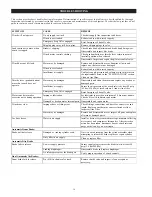
Страница 16: ...ts Insufficient air supply Ensure the air pressure at the winch inlet is at least 90 psig 6 3 bar 630 kPa at rated volume Clean air line filter Emergency Stop Valve engaged Reset Emergency Shut off valve Motor runs hot or makes excessive noise during operation Improper lubrication Set lubricator to provide a minimum of 6 drops per minute Check oil level in lubricator and motor Damaged or broken mo...

Страница 17: ...rning winch to service 3 After winch operation allow oil to settle before topping off 4 Always collect lubricants in suitable containers and dispose of in an environmentally safe manner Winch Reduction Gear and Disc Brake Lubrication Refer to Dwg MHP0501 The reduction gear and disc brake are filled and shipped with oil from the factory Check oil level before initial winch operation These component...

Страница 18: ...il but not long enough for it to freeze Failure to drain the water when the winch is to remain idle for an extended period at low temperature may result in the oil splasher freezing fast Drain the water then refill to the level plug If desired all the oil may be drained at the end of the shift and the motor refilled with new oil Recommended Motor Lubricant Temperature Recommended Viscosity Under 3...

Страница 19: ...xtremely tough and durable coating designed to take the toughest treatment without chipping or peeling Special steps must be taken to protect the coating when parts are removed replaced and if excessive environmental or operational conditions have damaged the coating Cleaning Parts The area to be coated must be clean and free from loose coating Remove any surface corrosion To paint thermoplastic c...

Страница 20: ...d capscrew 120 in place Check that capscrew 120 cannot turn when capscrew 130 is tightened If capscrew 120 turns replace locking pellet 129 Automatic Brake 1 Loosen jam nut 117 closest to plunger 114 2 Adjust band assembly using capscrew 120 a To loosen band brake turn capscrew 120 in the counterclockwise direction b To tighten band brake turn capscrew 120 in the clockwise direction NOTICE If the ...

Страница 21: ...is located 180 degrees from the air fitting The heads of these two capscrews sit deeper into the counterbores of the brake cover Do not remove these two capscrews until the brake has been separated as an assembly from the winch and the directions in the Disc Brake Disassembly section have been reviewed 10 Disconnect and remove brake hose 75 Remove six capscrews 1 attaching disc brake assembly to o...

Страница 22: ...assembly Removal or damage to the O ring requires replacement of the poppet assembly to ensure proper valve operation b Remove retainer ring 429 Pull poppet assembly 423 along with poppet seat 428 and valve piston 431 from valve body 410 c Reach into valve body and remove spring 422 and poppet restrictor 402 d Remove retainer ring 432 and separate valve piston 431 and poppet seat 428 e Remove and ...

Страница 23: ...e remaining cylinder liners and pistons as described in steps 7 and 8 To remove the crank assembly all pistons and cylinder liners must be removed 10 Crank assembly 231 can now be removed with the oil slinger 230 by pulling straight out from the motor housing 217 Use care while guiding the connecting rods 206 through the inside of the motor housing Crankshaft Disassembly 1 Remove cotter pin 236 an...

Страница 24: ...utput shaft 28 from drum 62 Remove capscrews 504 and separate parts Reduction Gear Refer to Dwg MHP0649 1 Place the reduction gear assembly on a clean work bench such that reducer housing 59 with oil seal 58 is down 2 Remove thrust washer 34 and output carrier assembly 52 3 Remove the input carrier assembly 69 by grasping the intermediate sun gear 45 and removing as an assembly This also removes t...

Страница 25: ...ndling 6 Remove all nicks and burrs caused by lockwashers Assembly General instructions use all new gaskets and seals replace worn parts assemble parts using match marks applied during disassembly Compare replacement parts with originals to identify installation alignments lubricate all internal parts with rust and oxidation inhibiting lubricant ISO VG 100 30W Thermoplastic Coated Parts Assembly C...

Страница 26: ... installed Control Valve Assembly NOTICE Lubricate all O rings with DOW CORNING 111 lubricant Failure to use lubricant or the use of other lubricants can cause valve malfunction Contact the factory if recommended lubricant is not available Use a correctly sized tap and die to clean threaded holes and fastener threads prior to assembly Ensure machined surfaces are clean and free from damage which c...

Страница 27: ... will be removed in a following step 16 Align poppet seat with valve body and using fingers press poppet seat into valve body 17 Secure in place using retainer ring 429 NOTICE Install pin 406 in step 18 only enough to determine clearance requirements of step 19 Do not fully install pin until directed 18 On lever operated control valves install pin 406 in shaft 401 on the handle end of valve This i...

Страница 28: ...sh a 0 06 0 12 inch 1 5 3 0 mm clearance between the interior washer face and the poppet assembly 423 end face Secure in place with cotter pin 414 with ends bent back to hold in place 2 Press pin 463 into handle 449 until one end protrudes approximately 1 16 inch 1 6 mm 3 Slide O ring 460 down handle into groove and lubricate Dwg MHP1024 3 For units with dual air brakes repeat step 2 for second va...

Страница 29: ...haft to establish an 0 06 0 12 inch 1 5 3 0 mm clearance between the interior washer face and the poppet assembly 423 end face Secure in place with cotter pin 414 with ends bent back to hold in place 2 Lubricate threads and install capscrews 437 and 439 washers 433 gasket 411 and valve cap 438 to valve body 410 Tighten capscrews to 54 60 inch lbs 20 22 Nm Pendant Operated Valve End Cap Assembly Re...

Страница 30: ...e with the hole in the intermediate carrier 35 Carefully insert the pin and tap to install the planet pin 36 while driving out the locator pin When installed and with the holes lined up in the carrier and in the pin install roll pin 37 to secure in place Verify end clearance Repeat for the remaining planet gear assemblies 5 Place thrust washers 55 and thrust bearing 56 on input sun gear 54 Install...

Страница 31: ... with sealant Install second jam nut 117 to approximately the middle of the thread length Thread capscrew 120 into bottom of plunger 114 a minimum of five thread lengths Lock in place against plunger using jam nut 117 Adjust brake as described in the Drum Band Brake Adjustment section Manual Drum Band Brake 1 Coat the bearings with LubriPlate MO LITH No 2 or equivalent lubricant and install bearin...

Страница 32: ...4 Nm Install exhaust valve 79 elbow fitting 80 and connect air hose 75 to elbow fitting 13 Winch drum must rotate freely in the haul in direction and must not rotate in the payout direction unless air is applied to the brake when assembled properly Testing Operational Test Prior to initial use all new altered or repaired winches shall be tested to ensure proper operation 1 Check oil level in motor...

Страница 33: ...3 44 Pendant Operated Pilot Control Valve Assembly Parts List 45 Remote Pendant Assembly Parts Drawing MHP0934 and Parts List 46 Freespool Assembly Parts Drawing MHP0927 and Parts List 47 Shuttle Valve Assembly Parts Drawing MHP0764 48 Shuttle Valve Assembly Parts List 49 Emergency Stop and Overload Assembly Parts Drawing MHP1188 50 Emergency Stop and Overload Assembly Parts List 51 Open Frame Fac...

Страница 34: ...34 WINCH ASSEMBLY PARTS DRAWING ...

Страница 35: ... Planet 3 23893 70 O Ring 1 51459 44 Thrust Washer 1 20406 71 Motor Adapter K5B 1 22034 69 Input Carrier Assembly 2 1 23897 72 Cover 1 24440 45 Intermediate Sun Gear 1 23894 73 Capscrew 6 71311674 46 Retainer Ring 2 71113278 74 Washer 8 71274807 47 Carrier Planet 1 23898 80 Capscrew 6 71113161 49 Pin Planet 3 20386 81 Capscrew 8 71264709 50 Bearing Roller 108 71113252 82 Corner Bar 4 21882 51 Gear...

Страница 36: ...36 MOTOR ASSEMBLY PARTS DRAWING ...

Страница 37: ... Ring 5 Order Item 202 243 Gasket 2 K5B 928 208 Cylinder Liner 5 K5B L505 47 244 O Ring 1 20A11CM248 209 Head Gasket 1 Set K5B 507 5 246 Grease Fitting 1 53095 210 Vent Cap Assembly 1 K5B A303 247 Rotary Valve Housing 1 K5B 545 213 Eye Bolt 2 KU 888 248 Gasket 1 K5B 547 216 Mounting Flange 1 K5B 502 250 Rotary Valve 1 K5B 526EQ R 217 Motor Housing 1 K5B 501A 251 Seal Ring 1 Set K5B 607A 218 Pipe P...

Страница 38: ...38 DISC BRAKE ASSEMBLY PARTS DRAWING ...

Страница 39: ... 1 71053748 10 Inner Race 1 24038 25 Brake Shaft 1 24039 11 Spacer 2 19007 79 Valve Exhaust 1 71047898 12 Outer Race 1 22032 80 Elbow Fitting 1 24141 13 Friction Plate 5 71126874 Sideframe Brake Hose 65 Short Drum 15 in 1 24674 75 Short Drum 15 in 1 23230 63 Long Drum 27 in 24675 Long Drum 27 in 23230 75 Recommended spare Disc Brake Assembly includes items 1 through 25 As viewed from the brake end...

Страница 40: ...40 DRUM BAND BRAKE ASSEMBLY PARTS DRAWING ...

Страница 41: ...71267413 2 71264790 1 119 Pivot Bar 1 23755 120 Capscrew 1 71267405 71288039 121 Cylinder 1 23889 122 O Ring 1 52536 123 Piston 1 23884 124 Spring 1 71144943 125 Cover 1 23887 126 Retainer Ring 1 71126668 127 Spring 1 71144935 128 Washer 1 71145080 129 Locking Pellet 1 23737 130 Capscrew 2 52160 131 Cam Plate 1 21893 132 Retainer Ring 1 71145122 133 Washer 1 71137905 134 Bearing Sleeve 1 23749 135...

Страница 42: ...42 LEVER OPERATED CONTROL VALVE ASSEMBLY PARTS DRAWING ...

Страница 43: ...Handle 1 23747 418 Capscrew 2 71261747 450 Valve Cap 1 23607 419 Gasket 1 23744 460 O Ring 1 71146963 420 Exhaust Poppet 1 23516 461 Cross Shaft 1 23746 421 Plug 1 51897 462 Spring 1 71146948 422 Spring 2 71138028 463 Pin 1 71146955 423 Inlet Poppet Assembly 2 24139 464 Detent Plate 1 23748 424 Gasket 1 71264725 465 Capscrew 3 53807 425 Fitting Elbow 71262299 469 Knob 1 71138051 426 O Ring 2 52662...

Страница 44: ...44 PENDANT OPERATED PILOT CONTROL VALVE ASSEMBLY PARTS DRAWING ...

Страница 45: ...O Ring 2 71145650 420 Exhaust Poppet 1 23516 456 Seal Cup 2 23597 421 Plug 1 51897 457 O Ring 2 71138234 422 Spring 2 71138028 458 Setscrew 2 71148779 423 Inlet Poppet Assembly 2 24139 459 Retainer Spring 2 24041 424 Gasket 1 71264725 465 Capscrew 3 53807 425 Fitting Elbow 71262299 470 Capscrew 2 71303671 426 O Ring 2 52662 471 Seal Washer 2 71303838 427 O Ring 2 51768 479 Shuttle Valve Body 1 241...

Страница 46: ... 2 71271142 625 Pin Dowel 2 71261341 Spring Emergency Stop 1 71261390 626 Cover 1 24443 641 Button 3 24155 628 Gasket 2 71044960 642 O Ring 3 50557 631 Fitting 2 71044937 643 Label 1 Set 71261309 632 Spring 2 71263081 645 Pendant Hose length 6 ft 1 26028 633 Fitting 2 71273114 646 Pendant Extension Assembly 1 24259 XX Recommended spare Pendant Assembly includes items 620 through 645 Pendant Extens...

Страница 47: ... 22259 26 Outboard Upright 1 25566 507 Free Spool Shifter 1 22258 28 Output Shaft 1 21019 508 Plunger 1 71138283 404 O Ring 1 71137988 509 Handle 1 22269 500 Free Spool Assembly 1 22255 510 Pin 1 71053722 501 Capscrew 6 71266613 511 Washer 6 71303408 502 Capscrew 6 71138275 512 Warning Label 1 contact factory 503 Housing 1 22256 Recommended spare Free Spool Assembly Item 500 includes items 2 7 18 ...

Страница 48: ...48 SHUTTLE VALVE ASSEMBLY PARTS DRAWING ...

Страница 49: ...33 483 Tube Fitting 1 71044937 Lever Operated Air Valve 479 Shuttle Valve Body 1 23739 494 Nipple Fitting 71262117 418 Capscrew 2 71261747 495 Elbow Fitting 71267173 419 Gasket 1 23744 629 Roll Pin 2 71039374 425 Elbow Fitting 71262299 630 Pin 1 71146674 435 Plug 71069009 Recommended spare Tubing colors noted on Dwg MHP0764 are for reference only Originally supplied units are marked with the color...

Страница 50: ...50 EMERGENCY STOP AND OVERLOAD ASSEMBLY PARTS DRAWING ...

Страница 51: ...6 Body 1 24200 528 Capscrew 4 71138077 530 Poppet Assembly 1 25837 531 O Ring 1 71137970 534 O Ring 2 50846 535 Ball 1 71126833 536 Spring 1 71263875 537 O Ring 1 71126825 538 Poppet Rod Assembly 1 25838 539 Spring 1 71261945 540 Rod Emergency Stop 1 24255 541 O Ring 1 71303978 542 Poppet Guide 1 24256 543 O Ring 1 71137962 544 Retainer Ring 1 71157507 545 Palm Valve Knob 1 24257 546 Label 1 71266...

Страница 52: ...52 OPEN FRAME FACE WINCH ASSEMBLY PARTS DRAWING ...

Страница 53: ... 25548 68 Upright Motor End 1 25567 572 Capscrew 4 71306450 81 Capscrew 4 71264709 573 Sideframe Motor End 1 25549 82 Corner Bar 2 21882 574 Capscrew 4 71306443 65 Sideframe 570 Bar Short Drum 1 24674 Short Drum 2 Long Drum 24675 Long Drum 25550 75 Brake Hose Short Drum 1 23230 63 Long Drum 23230 75 Open Frame Face Kit Assembly includes Items 570 through 574 Short Drum 1 Long Drum 1 25546 Contact ...

Страница 54: ...DESCRIPTION OF PART QUANTITY TOTAL PART NUMBER Motor Muffler and Fittings 710 Muffler 1 50594 711 Elbow Fitting 1 71106439 712 Reducer 1 71057459 Control Valve Muffler and Fittings 713 Nipple Fitting 1 71311260 714 Elbow Fitting 1 54299 715 Muffler 1 71264360 ...

Страница 55: ... PART NUMBER 590 Drum Guard Short Drum 12 and 15 inch 1 23836 Drum Guard Long Drum 24 and 27 inch 23506 591 Bracket 2 23608 592 Capscrew 4 71261739 593 Washer As Required 71049423 Drum Guard Assemblies includes Items 590 through 593 Short Drum 12 and 15 inch 1 23835 Long Drum 24 and 27 inch 1 23507 ...

Страница 56: ...TAL PART NUMBER DESCRIPTION OF KIT QTY TOTAL PART NUMBER Adapter Rail Kit for FA5A Short Drum to K6U Foot Print 1 24333 Adapter Rail Kit for FA5A Long Drum to K6U Foot Print 1 24332 ITEM NUMBER DESCRIPTION OF PART QUANTITY TOTAL PART NUMBER 575 Filter 1 F42 0B 000 576 Pipe Nipple 1 51670 577 Regulator 1 R30 0B G00 578 Pipe Nipple 3 51704 579 Pipe Bushing 2 Contact factory 580 Lubricator 1 L40 0B G...

Страница 57: ...57 WINCH LABEL TAG LOCATION AND PART NUMBER REFERENCE DRAWING ...

Страница 58: ...Material Handling Douai Operations 111 avenue Roger Salengro 59450 Sin Le Noble France Phone 33 3 27 93 08 08 Fax 33 3 27 93 08 00 PARTS ORDERING INFORMATION The use of other than Ingersoll Rand Material Handling replacement parts may adversely affect the safe operation and performance of this product For your convenience and future reference it is recommended that the following information be rec...

Страница 59: ...iginal user its Hoists and Winches Products to be free of defects in material and workmanship for a period of one year from the date of purchase I R will repair without cost any Product found to be defective including parts and labor charges or at its option will replace such Products or refund the purchase price less a reasonable allowance for depreciation in exchange for the Product Repairs or r...

Страница 60: ...9040 Fax 514 695 0963 British Columbia 201 6351 Westminster Hwy Richmond B C V7C 5C7 Phone 604 278 0459 Fax 604 278 1254 Latin America Operations Ingersoll Rand Production Equipment Group 730 N W 107 Avenue Suite 300 Miami FL 33172 3107 Phone 305 559 0500 Fax 305 559 7505 Europe Middle East and Africa Ingersoll Rand Material Handling Douai Operations 111 avenue Roger Salengro 59450 Sin Le Noble Fr...

Отзывы: