


32
3.
Install assembly on support plate (19).
4.
Install twelve springs (17) in holes on inside of support
plate (19).
5.
Install gasket (18) and pressure plate (15).
6.
Determine correct alignment of cover (2), housing (6) and
support plate (19) by checking matchmarks placed during
disassembly, or by placing housing on support plate and
matching capscrew holes.
7.
Correctly align with dowel slots on the housing (6) and
alternately install six separator plates (14) and five friction
plates (13), beginning with a separator plate. Align the
outer three indentations on plates to form a single groove.
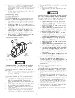
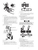
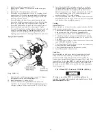
8.
Install the three dowel pins (9) in housing (6). Apply
Loctite
®
515 sealant on mating surfaces of housing and end
cover (2). Install housing by aligning dowel pins with
separator (13) and friction plate (14) grooves and, also
aligning capscrew holes in housing with holes in end cover.
(Dwg. MHP1197)
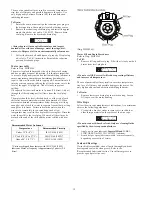
9.
Install ring (4), and diaphragm support plate (5). Support
plate radius must be next to diaphragm (3).
10. Install diaphragm (3) and cover (2).
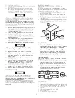
11. Locate as shown on Dwg. MHP1230 and install two
capscrews (1). Evenly and alternately tighten capscrews to
compress springs. Torque capscrews to 18 ft lbs (24 Nm).
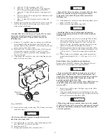
12. Install brake shaft (25) and place assembly on outboard
(opposite motor end) upright (26). Align capscrew holes
such that the breather (8) is slightly off top dead center.
Install six capscrews (1). Torque capscrews to 18 ft lbs (24
Nm). Install exhaust valve (79), elbow fitting (80) and
connect air hose (75) to elbow fitting.
13. Winch drum must rotate freely in the haul-in direction and
must not rotate in the payout direction, unless air is applied
to the brake, when assembled properly.
Testing
Operational Test
Prior to initial use, all new, altered or repaired winches shall be
tested to ensure proper operation.
1.
Check oil level in motor, reduction gear assembly and disc
brake are correct. Top off levels as required before
operation as described in the “LUBRICATION” section.
2.
To initially ‘break in’ new or overhauled motors, operate
winch without load, in both directions, for 2 hours at 100 -
200 RPM.
3.
Check operation of brakes. Adjust if necessary as described
in the "MAINTENANCE" section.
4.
Check operation of limit switches, locking mechanisms and
all safety devices when equipped.
5.
Check foundation mounting fasteners are secure.
6.
Install drum guard when provided.
Load Test
Prior to initial use, all new, extensively repaired, or altered
winches shall be load tested by or under the direction of a
person trained in safety and operation of this winch and a
written report furnished confirming the rating of the winch. Test
loads shall not be less than 100% of rated line pull at mid drum
and must not exceed 125% of the rated line pull at mid drum.
To test the winch at 125% of the rated load at mid drum apply
the following load:
FA5A Winch 125% Test Load
12,500 lb. (9,058 kg)
NOTICE
• Testing to more than 125% of rated line pull may be
required to comply with standards and regulations set forth
in areas outside the USA.
Содержание force5 FA5A-LAK1
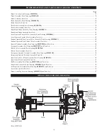
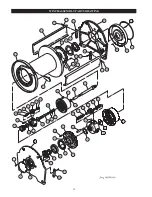
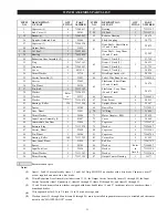
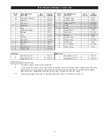
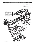
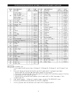
Страница 34: ...34 WINCH ASSEMBLY PARTS DRAWING ...
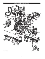
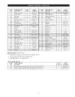
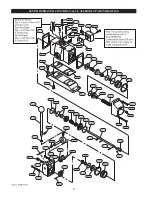
Страница 36: ...36 MOTOR ASSEMBLY PARTS DRAWING ...
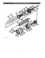
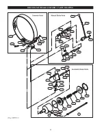
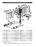
Страница 38: ...38 DISC BRAKE ASSEMBLY PARTS DRAWING ...
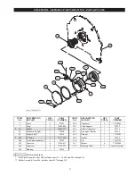
Страница 40: ...40 DRUM BAND BRAKE ASSEMBLY PARTS DRAWING ...
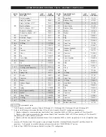
Страница 42: ...42 LEVER OPERATED CONTROL VALVE ASSEMBLY PARTS DRAWING ...
Страница 44: ...44 PENDANT OPERATED PILOT CONTROL VALVE ASSEMBLY PARTS DRAWING ...
Страница 48: ...48 SHUTTLE VALVE ASSEMBLY PARTS DRAWING ...
Страница 50: ...50 EMERGENCY STOP AND OVERLOAD ASSEMBLY PARTS DRAWING ...
Страница 52: ...52 OPEN FRAME FACE WINCH ASSEMBLY PARTS DRAWING ...
Страница 57: ...57 WINCH LABEL TAG LOCATION AND PART NUMBER REFERENCE DRAWING ...


