


28
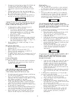
(Dwg. MHP1027)
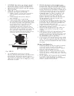
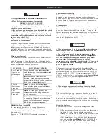
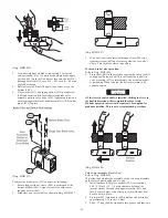
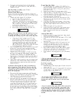
3.
With an allen wrench inserted through sleeve (408) slot,
tighten setscrew (407) until secure against the far wall of
sleeve. This locks the sleeve in position.
To check brake valve operation:
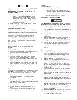
Refer to Dwg. MHP1026.
1.
Press shaft (401) in the direction causing the sleeve to shift
and engage the lower ball. This will cause the top ball in
valve assembly (413) to immediately rise as the lower ball
is pushed up. When released, the ball must return to its
neutral position.
NOTICE
• If the lever throttle handle is installed, shifting the lever in
the haul-in direction will accomplish the same result.
Pendant operated valves would require air be supplied for
pendant operation. This is not a recommended procedure.
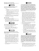
(Dwg. MHP1026)
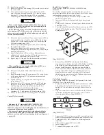
Valve Cap Assembly (Handle End)
Refer to Dwg. MHP0654.
The following describes the assembly of the valve cap assembly
on the lever control handle end of valve.
1.
Install washers (434) place on shaft (401) to establish a
0.06 -0.12 inch (1.5 - 3.0 mm) clearance between the
interior washer face and the poppet assembly (423) end
face. Secure in place with cotter pin (414) with ends bent
back to hold in place.
2.
Press pin (463) into handle (449) until one end protrudes
approximately 1/16 inch (1.6 mm).
3.
Slide ‘O’ ring (460) down handle into groove and lubricate.
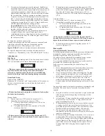
(Dwg. MHP1024)
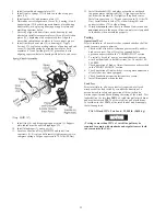
3.
For units with dual air brakes, repeat step 2 for second
valve assembly (413). On units with a single brake, apply
Loctite
®
609 to pin (412) and press into valve body (410)
[through the air inlet]. Leave 0.16 - 0.25 inch (4 - 6.4 mm)
exposed at the top.
4.
Rotate sleeve (408) until long section of sleeve is on the
bottom (180°).
5.
Place washer (417) and spring washer (416) on capscrew
(465) and install in hole located between brake valve
assembly ports in valve body (410). Tighten capscrew and
ensure spring washer locks brake assembly(s) (413) and/or
pin(s) (412) in place.
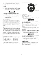
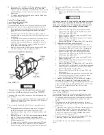
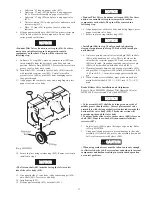
(Dwg. MHP1227)
To adjust the brake valve (413) conduct the following:
1.
Ensure long section of sleeve (408) is positioned at the
bottom of shaft (401). Align slot in sleeve with center
(angled) hole in shaft.
2.
Slide sleeve up to steel ball as shown in Dwg. MHP1027.
Содержание force5 FA5A-LAK1
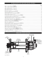
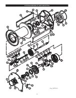
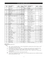
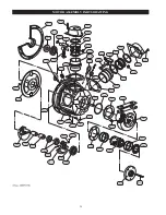
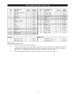
Страница 34: ...34 WINCH ASSEMBLY PARTS DRAWING ...
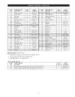
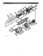
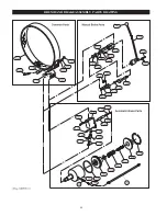
Страница 36: ...36 MOTOR ASSEMBLY PARTS DRAWING ...
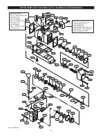
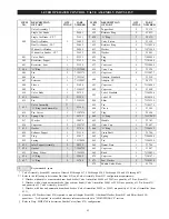
Страница 38: ...38 DISC BRAKE ASSEMBLY PARTS DRAWING ...
Страница 40: ...40 DRUM BAND BRAKE ASSEMBLY PARTS DRAWING ...
Страница 42: ...42 LEVER OPERATED CONTROL VALVE ASSEMBLY PARTS DRAWING ...
Страница 44: ...44 PENDANT OPERATED PILOT CONTROL VALVE ASSEMBLY PARTS DRAWING ...
Страница 48: ...48 SHUTTLE VALVE ASSEMBLY PARTS DRAWING ...
Страница 50: ...50 EMERGENCY STOP AND OVERLOAD ASSEMBLY PARTS DRAWING ...
Страница 52: ...52 OPEN FRAME FACE WINCH ASSEMBLY PARTS DRAWING ...
Страница 57: ...57 WINCH LABEL TAG LOCATION AND PART NUMBER REFERENCE DRAWING ...


