


31
9.
If equipped with drum band brake, attach band brake
assembly (104) as described in the ‘Drum Band Brake
Assembly’ section.
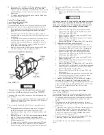
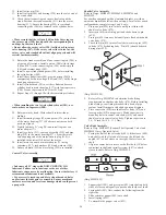
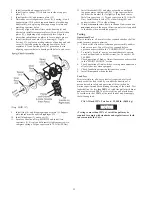
Drum Band Brake Assembly (optional feature)
Refer to Dwg. MHP0631.
Automatic Drum Band Brake:
For ease of assembly install bracket (106) and cylinder (121)
assemblies to motor end upright (68) prior to assembling upright
to drum.
1.
Assemble the brake cylinder (121) as follows:
a.
Install ‘O’ ring (122) on piston (123).
b.
Heavily coat the piston and cylinder rod with
“LubriPlate” MO-LITH No. 2 or equivalent lubricant.
Install ‘O’ rings (109) and (110) on cylinder rod (108).
Place cylinder rod (108) into piston (123) and secure
in place using retainer ring (111).
c.
Install piston assembly in brake cylinder (121).
d.
Install washer (128) and springs (124) and (127).
DANGER
• Springs (124) and (127) exert a considerable force on cover
(125) when assembled . Extreme care must be taken when
assembling and installing cover (125) and retainer ring (126).
e.
Using a press, slowly compress cover (125) and
springs until the retainer ring groove is accessible.
Install retainer ring (126). To ensure that retainer ring
is properly installed, tap the end of the retainer ring
with a punch until the entire retainer ring rotates in
brake cylinder groove. Slowly release press and ensure
retainer ring securely holds cover in place.
2.
If not accomplished during ‘Winch Assembly’ steps, install
bracket (106) to inside of motor end upright (68) and
secure in place using capscrews (107) and (112). Torque
capscrews to 85 ft lbs (115 Nm).
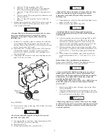
3.
Assemble roller (116) in plunger (114) and secure using
dowel pin (115). Heavily coat the plunger assembly with
“LubriPlate” MO-LITH No. 2 or equivalent lubricant.
Install spring (113) and plunger assembly in brake bracket
(106). Align groove in plunger towards hole in motor end
(68) upright.
4.
Align cylinder rod roller surface to groove in plunger. Turn
cylinder (121) clockwise until snug. Adjust cylinder (121)
such that the air hose connection port is horizontal and
towards the motor.
Conduct the following when the winch is assembled, but
prior to mounting to the foundation. The motor end of the
winch should be raised enough to allow access to the brake
components located on the inside surface of the inboard
(motor end) upright (68).
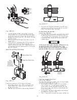
5.
Place spacer (105) between upper brake band flange and
bracket. Attach band assembly (104) to bracket (106) using
three capscrews (101), spacers (102) and spacer tubes
(103). Torque capscrews to 55 ft lbs (75 Nm).
6.
Install pivot bar (119) and capscrew (120) through lower
flange of brake band assembly (104). At lowest point of
threads, place a bead of Loctite® 680 and install jam nut
(117) fully. Jam nut threads must become coated with
sealant. Install second jam nut (117) to approximately the
middle of the thread length. Thread capscrew (120) into
bottom of plunger (114) a minimum of five thread lengths.
Lock in place, against plunger, using jam nut (117). Adjust
brake as described in the ‘Drum Band Brake Adjustment’
section.
Manual Drum Band Brake:
1.
Coat the bearings with “LubriPlate” MO-LITH No. 2 or
equivalent lubricant and install bearings (138) and (140) in
brake bracket (106). Install ‘O’ rings (137) and (141) in
brake bracket (106).
2.
Install eccentric shaft (135) in brake bracket (106).
3.
Install cam plate (131) on end of shaft (135). Install washer
(133), bearing sleeve (134) and retainer ring (132).
4.
Install assembly onto motor end upright (68) and secure in
place with capscrews (107) and (112).
5.
Attach brake band assembly (104) using capscrew (120).
Thread capscrew into cam plate only as necessary to hold
components together.
6.
Attach other end of band brake assembly (104) to brake
bracket (106) using capscrews (101), spacers (102), (103)
and (105). Torque capscrews at 52 to 57 ft lbs (70 to 78
Nm).
7.
Install brake handle (142) on shaft (135).
8.
Install assembly onto winch drum. Align brake bands on
drum brake surface. Install brake handle (142). Adjust
brake as described in the following ‘Adjusting Drum
Brake’ section.
Adjusting Drum Brake
1.
Pull back on handle to engage drum brake. Brake should
lock (eccentric going over center).
2.
With brake locked, the winch should support 125% of rated
load.
3.
To increase brake band load holding capacity tighten
capscrew (120).
4.
Once brake is adjusted to hold 125% of rated load, lock
adjustment by tightening capscrew (130). This causes
locking pellet (129) to press on capscrew (120) threads,
preventing movement but not damaging threads.
5.
Push forward on handle to release brake. Remove handle
(142) from eccentric shaft (135) and position it on shaft
such that the lower half is in a vertical position.
6.
Secure handle to shaft using capscrew (130) and washers
(143).
NOTICE
• When properly adjusted the brake should require
approximately 35 lbs (16 kg) of force to engage and ‘LOCK’
(eccentric going over center).
Disc Brake Assembly
Refer to Dwg. MHP1230.
1.
Install bearing (21) into support plate (19) and secure with
retainer ring (22).
2.
In this order, place spacer (11), sprag clutch (16), outer race
(12) and spacer (11) on inner race (10). Test sprag clutch
operation. Refer to Dwg. MHP1197.
NOTICE
• Correct sprag clutch installation prevents clockwise
rotation (brake engages) and allows counterclockwise
rotation when viewed from the cover (2) end of the brake
assembly.
WARNING
• Incorrect assembly of the sprag clutch will adversely affect
winch operation. In haul-in operation, sprag clutch will be
engaged resulting in restricted winch operation. In neutral
and payout positions, the sprag clutch can rotate resulting in
brake not holding load. Ensure the sprag clutch is correctly
installed.
Содержание force5 FA5A-LAK1
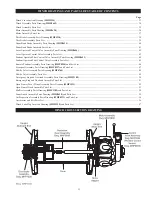
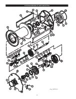
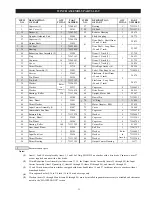
Страница 34: ...34 WINCH ASSEMBLY PARTS DRAWING ...
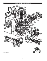
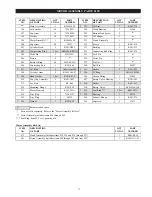
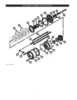
Страница 36: ...36 MOTOR ASSEMBLY PARTS DRAWING ...
Страница 38: ...38 DISC BRAKE ASSEMBLY PARTS DRAWING ...
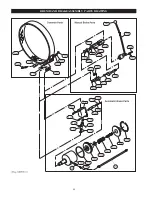
Страница 40: ...40 DRUM BAND BRAKE ASSEMBLY PARTS DRAWING ...
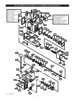
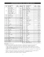
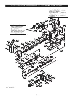
Страница 42: ...42 LEVER OPERATED CONTROL VALVE ASSEMBLY PARTS DRAWING ...
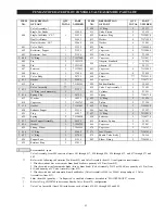
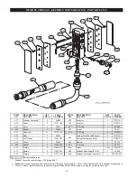
Страница 44: ...44 PENDANT OPERATED PILOT CONTROL VALVE ASSEMBLY PARTS DRAWING ...
Страница 48: ...48 SHUTTLE VALVE ASSEMBLY PARTS DRAWING ...
Страница 50: ...50 EMERGENCY STOP AND OVERLOAD ASSEMBLY PARTS DRAWING ...
Страница 52: ...52 OPEN FRAME FACE WINCH ASSEMBLY PARTS DRAWING ...
Страница 57: ...57 WINCH LABEL TAG LOCATION AND PART NUMBER REFERENCE DRAWING ...


