14
2.
FASTENERS. Check retainer rings, split pins, capscrews,
nuts, and other fasteners on winch, including mounting
bolts. Replace if missing or damaged and tighten if loose.
3.
DRUM and SHEAVES. Check for cracks, wear or damage.
Replace if necessary.
4.
WIRE ROPE. In addition to Frequent Inspection
requirements, also inspect for the following:
a.
Buildup of dirt and corrosion. Clean with steam or a
stiff wire brush to remove dirt and corrosion if
necessary.
b.
Loose or damaged end connection. Replace if
loose or damaged.
c.
Check wire rope anchor is secure in drum.
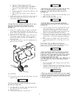
d.
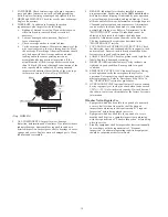
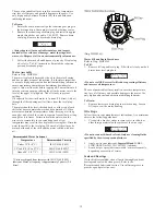
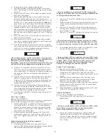
Verify wire rope diameter. Measure the diameter of the
wire rope from crown-to-crown throughout the life of
the wire rope. Recording of the actual diameter should
only be done with the wire rope under equivalent
loading and in the same operating section as
accomplished during previous inspections. If the
actual diameter of the wire rope has decreased more
than 1/64 inch (0.4 mm) a thorough examination of the
wire rope should be conducted by an experienced
inspector to determine the suitability of the wire rope
to remain in service. Refer to Dwg. MHP0056.
(Dwg. MHP0056)
5.
ALL COMPONENTS. Inspect for wear, damage,
distortion, deformation and cleanliness. If external evidence
indicates damage, disassemble as required to conduct a
detailed inspection. Inspect gears, shafts, bearings, sheaves,
springs and covers. Replace worn or damaged parts. Clean,
lubricate and reassemble.
6.
BRAKES. Individually test brakes installed to ensure
proper operation. Brakes must hold a 100% rated load at
mid drum without slipping. If indicated by poor operation
or visual damage, disassemble and repair brake(s). Check
all brake surfaces for wear, deformation or foreign deposits.
Clean and replace components as necessary. Adjustments
can be made to the drum band brake to compensate for
normal brake lining wear. Refer to ‘Adjustments’ in the
“MAINTENANCE” section. If brake band cannot be
adjusted to hold rated load, replace the brake band
assembly. Adjustments cannot be made to the disc brake.
The disc brake must be repaired as described in the
“MAINTENANCE” section.
7.
FOUNDATION or SUPPORTING STRUCTURE. Check
for distortion, wear and continued ability to support winch
and rated load. Ensure winch is firmly mounted and that
fasteners are in good condition and tight.
8.
LABELS AND TAGS. Check for presence and legibility of
labels. Replace if damaged or missing.
9.
DRUM GUARD (optional feature). Verify fasteners are
tight and in good condition. Ensure guard is in good
condition.
10. EMERGENCY STOP VALVE (optional feature). During
winch operation verify the emergency shut-off valve
operation. Valve must stop winch operation quickly. Valve
must reset properly. Refer to ‘Emergency Stop Valve’ in
the “OPERATION” section for procedures.
11. OVERLOAD DEVICE (optional feature). Ensure overload
device is properly set to stop the winch when loads exceed
150% (+/- 25%) of winch rated capacity. If winch does not
shut down, contact your distributor or the factory for repair
information.
Winches Not in Regular Use
1.
Equipment which has been idle for a period of one month
or more, but less than six months, shall be given an
inspection conforming to the requirements of “Frequent
Inspection” before being placed in service.
2.
Equipment which has been idle for a period of over six
months shall be given a complete inspection conforming
with the requirements of “Periodic Inspection” before being
place in service.
3.
Standby equipment shall be inspected at least semiannually
in accordance with the requirements of “Frequent
Inspection”. In abnormal operating conditions equipment
should be inspected at shorter intervals.
Содержание force5 FA5A-LAK1
Страница 34: ...34 WINCH ASSEMBLY PARTS DRAWING ...
Страница 36: ...36 MOTOR ASSEMBLY PARTS DRAWING ...
Страница 38: ...38 DISC BRAKE ASSEMBLY PARTS DRAWING ...
Страница 40: ...40 DRUM BAND BRAKE ASSEMBLY PARTS DRAWING ...
Страница 42: ...42 LEVER OPERATED CONTROL VALVE ASSEMBLY PARTS DRAWING ...
Страница 44: ...44 PENDANT OPERATED PILOT CONTROL VALVE ASSEMBLY PARTS DRAWING ...
Страница 48: ...48 SHUTTLE VALVE ASSEMBLY PARTS DRAWING ...
Страница 50: ...50 EMERGENCY STOP AND OVERLOAD ASSEMBLY PARTS DRAWING ...
Страница 52: ...52 OPEN FRAME FACE WINCH ASSEMBLY PARTS DRAWING ...
Страница 57: ...57 WINCH LABEL TAG LOCATION AND PART NUMBER REFERENCE DRAWING ...


