


7
2.3 Rear Panel Introduction
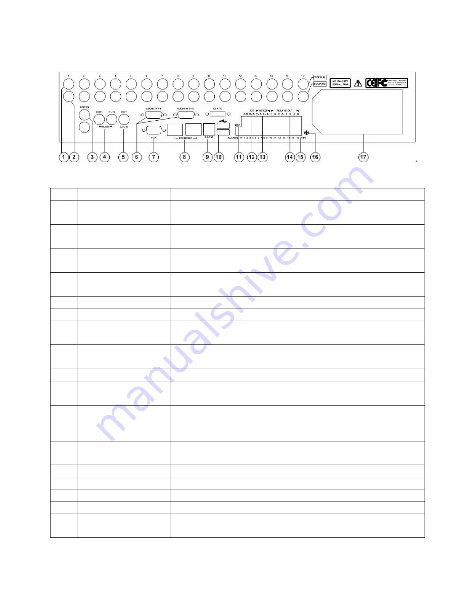
Figure 2-1 Rear Panel
No. Item
Description
1 VIDEO
IN
Standard BNC connectors to connect with analog video device for 16-ch analog video
inputs.
2 LOOPING
Standard BNC connectors to connect with monitor, matrix and other devices for 16-ch
analog video looping output.
3 LINE
IN
For intercom, 1-ch audio input, standard BNC connector to connect with audio input
device(microphone)
4 VIDEO
OUT
Standard BNC connector to connect with monitor for 2-ch analog video output. Video
output form OUT1 is consistent with VGA interface. OUT2 is for auxiliary video output.
5
AUDIO OUT
Standard BNC connector for 1-ch audio output.
6
AUDIO IN
16-ch audio input, 2 standard DB15 interface, with 2 DB15 to BNC connection cables.
7 VGA
Standard VGA interface to connect with VGA display device for video output and menu
display.
8 ETHERNET
PORT
2 10/100/1000Mbps self-adaptive Ethernet port for connection network device, RJ45
connector.
9
RS-232 INTERFACE
Connect with RS-232 serial device, RJ45 connector.
10 USB
INTERFACE
2 standard USB 2.0 interface to connect with USB devices for data backup, mouse
operation. Hot- swapping is supported.
11 TERMINATION
SWITCH
Open/Close the connection between RS422 bus and terminal resistor. It's disconnected
when the switch is at upper position (default). It is connected with terminal resistor
(120) when the switch is at lower position.
12 KEYBOARD
INTERFACE
Connect with control keyboard. D+ and D- connect to T+ and T- of the keyboard
respectively.
13
RS-422 INTERFACE
Connect with RS-422 serial device (such as Pan/Tilt encoder)
14
ALARM OUT
4-ch alarm output (4-ch switching value)
15
ALARM IN
16-ch alarm input (16-ch switching value)
16
GROUNDING TERMINAL
Grounding terminal of the DVR
17
POWER SUPPLY, POWER
SWITCH, FAN
AC 100~240V self-adaptive


