


45
Ethernet options
Y = yes (to allow the camera to be controlled by other sites over the Ethernet);
N = no (to restrict the camera from being controlled by other sites over the Ethernet).
Example
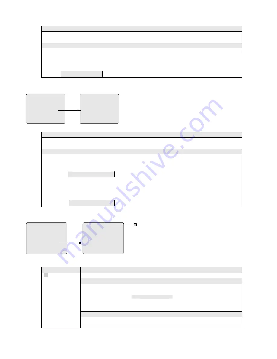
To restrict Camera 9 from being controlled by other sites over the Ethernet,
1)
Press the OPEN key in the IRIS section to display entries for Camera 9;
2)
Locate the cursor in the entry that indicates Monitor 9;
3)
Use the ACK key to select "N".
CAM
0009
ETHERNET
N
5.7.5 Monitor/Camera Access
ACCESS
1 KEYBOARD/MONITOR
2 KEYBOARD/CAMERA VIEW
3 KEYBOARD/CAMERA CTRL
4 MONITOR/CAMERA ACCESS
5 MONITOR/CONTACT ACCESS
6 KEYBOARD/REMOTE SITE
RETURN MAIN
MONITOR/CAMERA ACCESS
PREVIOUS MENU
MONITORS
CAM
0001
0002
0003
0004
0005
0006
0007
0008
001
Y
N
Y
Y
Y
Y
Y
Y
002
Y
N
Y
Y
Y
Y
Y
Y
003
Y
Y
Y
Y
Y
Y
Y
Y
004
Y
Y
N
N
Y
Y
Y
Y
The MONITOR/CAMERA ACCESS menu is used to restrict
selected monitors from displaying video images from specific
cameras.
The menu has multiple screen pages, each permitting setup
operations for 8 cameras and 4 monitors. Scroll the menu
page-down to setup more cameras and page-forward for more
monitors (see
Section 5.2
).
Monitor/Camera options
Y = yes (to allow the monitor to display video images from the camera);
N = no (to restrict the monitor from displaying video images from the camera).
Example
To allow Monitor 1 to display Camera 1 and prevent Monitor 5 from displaying Camera 9,
1)
Locate the cursor in the entry that indicates Monitor 1 and Camera 1;
2)
Use the ACK key to select "Y";
CAM
0001
01
Y
02
Y
03
Y
04
Y
3)
Press the ON key in the AUXILIARY section to display entries for Monitor 5;
4)
Press the OPEN key in the IRIS section to display entries for Camera 9;
5)
Locate the cursor in the entry that indicates Monitor 5 and Camera 9;
6)
Use the ACK key to select "N".
CAM
0009
05
N
06
Y
07
Y
08
Y
5.7.6 Monitor/Contact Access
ACCESS
1 KEYBOARD/MONITOR
2 KEYBOARD/CAMERA VIEW
3 KEYBOARD/CAMERA CTRL
4 MONITOR/CAMERA ACCESS
5 MONITOR/CONTACT ACCESS
6 KEYBOARD /REMOTE SITE
RETURN MAIN
MON/CONTACT TABLE - -
PREVIOUS MENU
MONITORS
ACN
0001
0002
0003
0004
0005
0006
0007
0008
001
N
N
N
N
N
N
N
N
002
N
N
N
N
N
N
Y
N
003
Y
N
N
N
N
N
N
N
004
N
Y
Y
N
N
N
N
N
A
The MONITOR/RELAY CONTACTS menu is used to associate
monitors with specific alarm contacts so that alarmed videos
triggered by these alarm contacts can be automatically switched to
corresponding monitors.
The menu has multiple screen pages, each permitting setup
operations for 8 alarm contacts and 4 monitors. Scroll the menu
page-down to setup more alarm contacts and page-forward for more
monitors (see
Section 5.2
).
Item
Function
A
MON CONTACT
TABLE
Selects one of the3 Monitor/Contact Tables to program.
Note
z
The menu provides 3 Monitor/Contact Tables (0-2), each defining a set of different
Monitor/Contact associations.
z
Table 0, displayed as
MON/CONTACT TABLE - -
, is the default table that indicates the
Monitor/Contact arming status currently active in the system.
z
ONLY Event Timers (see
Section 5.3.4
) can activate Tables 1-2.
To select a table to program,
1)
Move the cursor to the entry;
2)
Enter the desired table number (0-2), and press the ACK key to select.


