


3 - 3
IP
N 07
4-
46
2-
P1
C
Sion Operating Manual
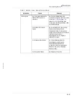
6. No signal
6a. Computer settings for
NiDAQ PCI board are
incorrect
6a. Perform Measurement &
Automation Explorer Self-Test (refer
to
steps 18 - 20). If Self-Test fails,
check computer Base Address, IRQ,
and DMA settings.
6b. NiDAQ PCI Board
failure
6b. Test NiDAQ PCI board using
National Instruments DAQ
Diagnostic Utility 2.0 (download
utility and instructions from National
Instruments web site at
http://digital.ni.com). Replace
NiDAQ PCI board.
6c. Breakout Box failure
6c. Check Breakout Box for
illuminated red LED next to
FABGUARD COMPUTER
connector. If LED is illuminated,
Breakout Box is bad. Replace
Breakout Box.
6d. Converter failure
6d. Replace Converter
Table 3-1 Symptom - Cause - Remedy Chart (continued)
Symptom
Cause
Remedy
Содержание Sion
Страница 1: ...O P E R A T I N G M A N U A L Sion RF Detector IPN 074 462 P1C ...
Страница 2: ......
Страница 6: ......
Страница 8: ......
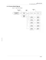
Страница 43: ...2 3 IPN 074 462 P1C Sion Operating Manual 2 2 5 System Block Diagram Figure 2 1 System Block Diagram ...
Страница 44: ...2 4 IPN 074 462 P1C Sion Operating Manual This page is intentionally blank ...
Страница 48: ...3 4 IPN 074 462 P1C Sion Operating Manual This page is intentionally blank ...
Страница 50: ...4 2 IPN 074 462 P1C Sion Operating Manual This page is intentionally blank ...
Страница 52: ...Index 2 IPN 074 462 P1C Sion Operating Manual This page is intentionally blank ...