


2 - 2
IP
N 07
4-
46
2-
P1
C
Sion Operating Manual
2.2 Instrument Overview
There are four modules that comprise the Sion system.
Detector, see
.
Converter, see
.
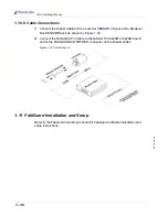
Breakout box, see
Data Acquisition Card, see
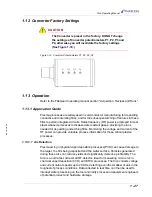
2.2.1 Detector
The Detector houses the voltage and current pickups. When attached to a RF
delivery strap with the appropriate clamp, the Detector outputs a RF signal
proportional to the RF voltage on the strap (Voltage Output) and a RF signal
proportional to the RF current flowing in the strap (Current Output). The output
coaxial connector of the Detector is attached to the Converter input connector.
2.2.2 Converter
The Converter is bulkhead mounted to a grounded wall of the tool in a location that
allows for attachment of the Detector cable. With the Detector attached, the
Converter will output current signals proportional to the log of the magnitude of the
Voltage and Current signals present at its input. Operating with its factory setting,
the Converter outputs will track the entire operating range of the Detector. Offset
and Gain adjustments are available to change the operating window if more gain
is desired for a particular application. The Converter outputs are current signals
that are sent over the CAT5 interface cable to the Breakout box.
2.2.3 Breakout Box
In the Breakout box, the Current and Voltage signals from one to four Converters
are converted back to voltage signals and routed to the appropriate channel of the
data acquisition card via the high density connector and interface cable.
5 V(dc) power for the Converter is routed through a fuse in the Breakout box. The
source of the 5 V(dc) power is the PC power supply, which is made available at the
interface connector of the data acquisition card.
2.2.4 Data Acquisition Board in PC
On the PC based Data Acquisition Board, the Current and Voltage signals are
multiplexed to the input of an Analog to Digital converter. The converted values are
then stored for use by the FabGuard software running on the PC, for process
monitoring and various data analysis functions.
Содержание Sion
Страница 1: ...O P E R A T I N G M A N U A L Sion RF Detector IPN 074 462 P1C ...
Страница 2: ......
Страница 6: ......
Страница 8: ......
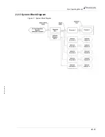
Страница 43: ...2 3 IPN 074 462 P1C Sion Operating Manual 2 2 5 System Block Diagram Figure 2 1 System Block Diagram ...
Страница 44: ...2 4 IPN 074 462 P1C Sion Operating Manual This page is intentionally blank ...
Страница 48: ...3 4 IPN 074 462 P1C Sion Operating Manual This page is intentionally blank ...
Страница 50: ...4 2 IPN 074 462 P1C Sion Operating Manual This page is intentionally blank ...
Страница 52: ...Index 2 IPN 074 462 P1C Sion Operating Manual This page is intentionally blank ...