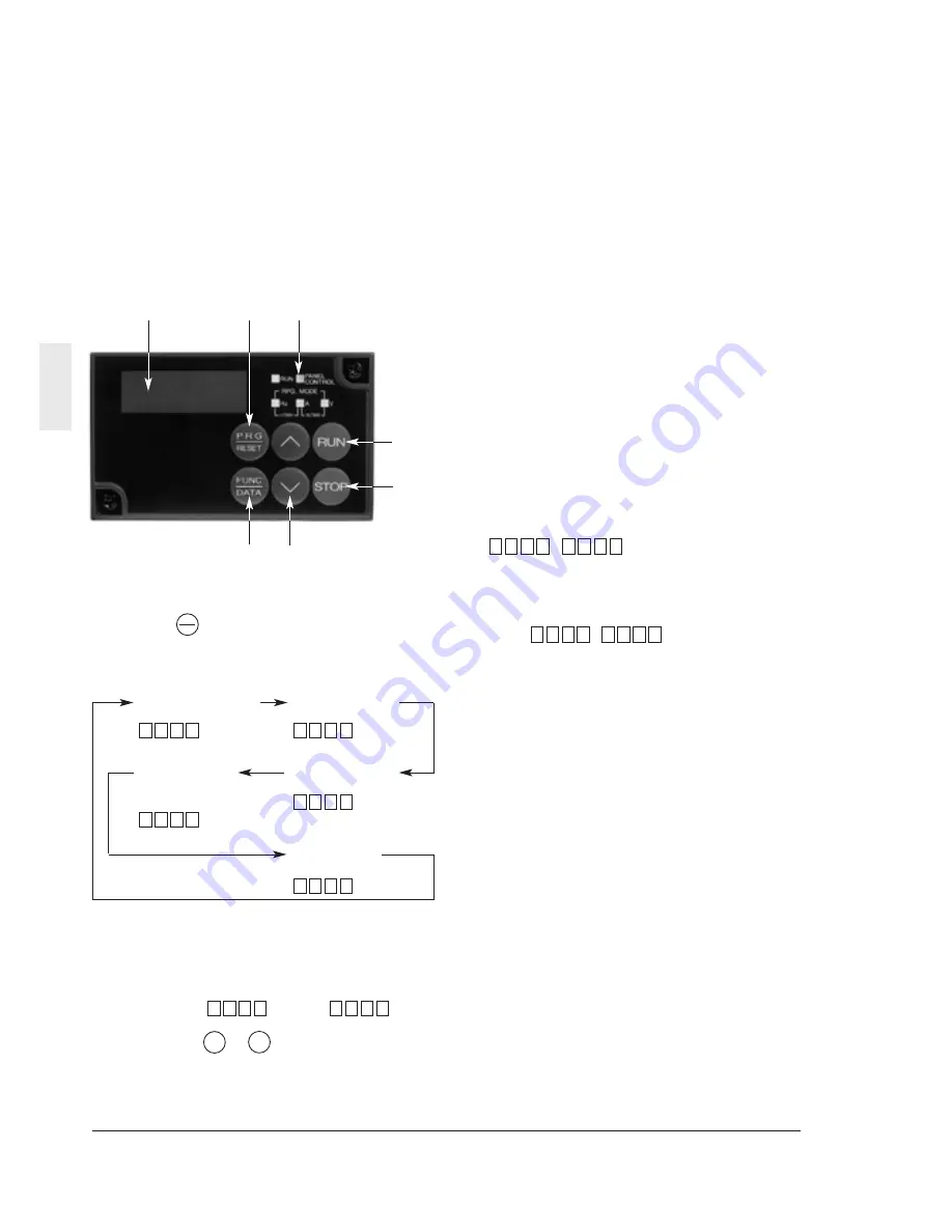
IMO VXSM150-1 Скачать руководство пользователя страница 27

Digital display

Various function codes and data codes for
programming are shown.
The output frequency, output current and
other data are displayed during operation,
and the cause of a trouble is displayed
using codes when protective function
works.

Program (PRG)/RESET key

Press this key to switch over between the
regular operation mode and programming
mode. Use this key to reset an alarm
stopping state after activation of a protective
function.

Unit and operation mode display

The unit of the data displayed at the digital
display is indicated with an LED. The
program mode is indicated. The PANEL
CONTROL lamp lights up in the keypad
panel operation mode.

RUN key

Press this key to start operation. An LED
lights up during operation. When data code

=

, the key does not

function.

STOP key

Press this key to stop operation. When data
code 

=

, this key does not

function.

Up/down keys

Press these keys to increase  or decrease
the frequency or speed.
In the programming mode, use these keys
to change the function code or data setting.

Function/Data key

Use this key to switch over between
frequency display, output current display
and other display in the regular operation
mode. In the programming mode, use this
key to retrieve or write various function
codes and various function data.

1

2

0

F

1

2

0

F

4-1

Keypad Panel

4

(1) Monitor display mode

In the regular operation mode, press the
key   to switch between frequency
display, output current display and other
display.

4. Keypad Panel

The keypad panel is provided with various
functions such as operation (frequency setting
and start/stop commands) from the keypad
panel, monitor and alteration of function code
data, and various confirmation functions.
Be familiar with the operation method of each
function before starting operation.

4-1

Appearance of Keypad Panel

FUNC

DATA

Output frequency *

1

0

0

0.

6

Output current *

2

0

2

1.

Output voltage *

2

0

0

2

Synchronization
rotation speed *

2

0

0

0

1

Line speed *

2

0

0

0

1

*1: In the PID control mode (when function H20

is at "1" or "2"), the value is in the percent
display and the dot at the least significant
digit always lights up.

Example: 10%: 

, 100%: 

*2: Press the       ,       key during display of

these data to display the frequency setting.

0.

0.

0

1

0.

0.

1

V

V

Содержание VXSM150-1

Страница 1: ...Instruction manual IMO Jaguar VXSM General Purpose Inver ter Single Phase 230V input 0 4 2 2kW Three Phase 415V input 0 4 7 5kW ...

Страница 2: ...ions 5 30 Alternative Motor Parameters A Functions 5 38 Optional Functions O Functions 5 39 6 Protective Operation 6 1 6 1 List of Protective Operations 6 1 6 2 Alarm Reset 6 2 7 Troubleshooting 7 1 7 1 When Protective Function Activates 7 1 7 2 When Motor rotates Incorrectly 7 5 8 Maintenance and Inspection 8 1 8 1 Daily Inspection 8 1 8 2 Periodic Inspection 8 1 8 3 Measurement of Current and Vo...

Страница 3: ......

Страница 4: ...VXSM is designed to drive a three phase induction motor Do not use it for single phase motors or for other purposes Otherwise fire could occur VXSM may not be used for a life support system or other purposes directly related to human safety Though VXSM is manufactured under strict quality control install safety devices for applications where serious accidents or material losses are foreseen in rel...

Страница 5: ...top inverter operation Otherwise failure could occur Do not touch the heat sink and braking resistor because they become very hot Otherwise burns could occur Setting the inverter to high speeds is easy Check the performance of the motor and machines before changing the setting Otherwise injuries could occur The brake function of the inverter does not provide mechanical holding means Injuries could...

Страница 6: ...lit and check the DC voltage across the P and N terminals to be lower than 25Vdc Otherwise electric shock could occur Maintenance and inspection and parts replacement should be made only by qualified persons Take off watch rings and other metallic matter before starting work Use insulated tools Otherwise electric shock or injuries could occur GENERAL PRECAUTIONS Drawings in this manual may be illu...

Страница 7: ...ter has to be installed in environment of pollution degree 2 If the environment is pollution degree 3 or 4 the inverter has to be installed in a cabinet of IP54 or higher 7 Use a cable according to EN60204 Appendix C 8 Install the inverter AC or DC reactor input or output filter in an enclosure to prevent a human body from touching directly this equipment 1 When a person can touch each connecting ...

Страница 8: ...power supply and the inverter referring to the table below 1 Use copper wires of allowable maximum temperature 60 or 75 degree C 2 Use UL certified AC600V Class J fuse 7 The inverters VXSM40 1 to 220 1 are suitable for use on a circuit capable or delivering not more than 20 000 rms symmetrical amperes 240V maximum 8 The inverters VXSM40 3 to 750 3 are suitable for use on a circuit capable or deliv...

Страница 9: ...output capacity rated output voltage output frequency range rated output current overload current rating SER NO Product number 0 1 0113R0001 Serial number of production lot Production month 1 to 9 January to September X Y or Z October November or December Production year Last digit of year 2 Check for breakage missing parts and dents or other damage on the cover and the main body given during tran...

Страница 10: ...rovided in the main circuit terminal block cover for the P1 P DB and N cable port Cut the barrier before wiring Keypad panel mounting screw Keypad panel Intermediate cover Ratings nameplate Terminal block cover Control cable port P1 P DB N cable port L1 R L2 S L3 T L1 L L2 N U V W cable port Grounding cable port ...

Страница 11: ... 1 Removing the control terminal block cover 4 0kW or below While lightly pushing the sides of the control terminal block cover at the catches lift the cover in the procedure shown in Fig 1 3 1 to remove it Fig 1 3 1 Removing the control terminal block cover Terminal block cover Control cable port L1 R L2 S L3 T cable port P1 P DB N cable port U V W cable port Cable cover Grounding cable port ...

Страница 12: ...cover at the catches slide toward you in the procedure shown in Fig 1 3 2 to remove it 3 Removing the terminal block cover 5 5 7 5kW Loose the screws indicated below and while lightly pushing the sides of the terminal block cover at the catches lift the cover in the procedure shown in Fig 1 3 3 to remove it Fig 1 3 2 Removing the main circuit terminal block cover ...

Страница 13: ...eypad panel in the procedure shown in Fig 1 3 4 During the procedure slowly remove the keypad panel right toward the top If the keypad panel is handled abruptly the connector will be broken Mounting screw M3 Fig 1 3 4 Removing the keypad panel Reverse the procedures to mount the terminal block cover and keypad panel ...

Страница 14: ...mosphere is adverse wrap the inverter in a vinyl sheet or the like when storing 3 If humidity may give an ill effect add a drying agent such as silica gel in the package prepared as described in item 2 Places not subjected to abrupt temperature changes or condensation or freezing To store for a long time The long term storage method of the inverter varies largely according to the environment of th...

Страница 15: ...heat sensitive device WARNING Install the inverter on a nonflammable material such as metal Otherwise fire could occur CAUTION Do not allow lint paper wood chips dust metallic chips or other foreign matter in the inverter or do not allow them attached to the heat sink Otherwise fire or an accident could occur 3 The temperature of the heat sink rises to about 90 degrees C during operation of the in...

Страница 16: ...l check the source voltage for the allowable voltage range specified on the nameplate and so on 2 Connect the grounding terminal according to national or local regulations to prevent electric shock fire or other accidents and to reduce electric noise 3 Use reliable crimp terminals for connection of cables to the terminals 4 After finishing wiring check the following a Check if the cables are conne...

Страница 17: ...itable for the rated voltage of the inverter 2 Optional part Use when necessary 3 Peripheral equipment Use when necessary 4 To connect a DC reactor DCR for power factor correcting remove the jumper between the P1 and P terminals Basic connection diagram Enclosure ...

Страница 18: ... the keypad panel If it is unavoidable to turn the main circuit power supply on or off to start or stop the inverter limit the frequency to once an hour or fewer if possible d Do not connect to a single phase power supply for 3 phase input inverter 2 Inverter output terminals U V W a Connect these terminals to a 3 phase motor with the correct phase sequence If the direction of rotation does not ma...

Страница 19: ...ernal braking resistor to the P and DB terminals of the inverter b Arrange devices so that the wiring length is within 5 m and twist or closely in parallel place the two cables 5 Inverter grounding terminal G Ground the grounding terminal G for safety and noise reduction without fail The metallic frame of electrical equipment must be grounded in accordance with national regulations to avoid electr...

Страница 20: ...ccording to the analog input current command 4 to 20 mAdc 0 to 100 Inverse mode operation 20 to 4 mAdc 0 to 100 2 The PID control feedback signal is input Input resistance 250 ohm 11 Common Common for analog signals FWD Forward operation Forward operation with FWD P24 ON and command deceleration and stop with FWD P24 OFF REV Reverse operation Reverse operation with REV P24 ON and command decelerat...

Страница 21: ...put 2 overload early warning signal and other signals are output to arbitrary ports at a transistor output Refer to terminal function E20 to 21 setting methods in section 5 2 Detail Description of Each Function Transistor output circuit specification Transistor output CMC Common Common for transistor output signal Isolated from Transistor output terminals CM and 11 P24 DC voltage supply Power supp...

Страница 22: ...he wiring as short as possible within 20 m and use shielded cables In principle ground the shield of the shielded cable if effects of external inductive noises are considerable connection to terminal 11 may be effective b Use twin contacts relay for weak signals if relay is used in the circuit Do not add a contact to terminal 11 c When the inverter is connected with an external device outputting t...

Страница 23: ...5 1 Screw size M4 Tightening torque 1 8N m VXSM40 3 VXSM75 3 VXSM50 3 VXSM220 3 Screw size M4 Tightening torque 1 8N m VXSM150 1 VXSM220 1 Screw size M4 Tightening torque 1 8N m VXSM400 3 Screw size M4 Tightening torque 1 8N m L1 L L2 N U V W DB P1 P N G G G G L1 L L2 N U V W DB P1 P N G G L1 R L2 S L3 T U V W DB P1 P N G G L1 L L3 N DB P1 P N U V W G G L1 R L2 S L3 T DB P1 P N U V W ...

Страница 24: ...ng VXSM550 3 VXSM750 3 Screw size M5 Tightening torque 3 5N m G G L1 R L2 S L3 T DB P1 P N U V W 1 Main circuit terminal block Continued 2 Control terminal block Screw size M2 5 Tightening torque 0 4N m 30A 30B Y1E C1 FM X1 X2 X3 X4 X5 CM 30C Y2E CMC 11 12 13 CM FWD REV CM P24 ...

Страница 25: ...accompanied by the voltage unbalance 4 Use crimp terminals with an insulating cover 2 3 5 Applicable Devices and Cable Sizes for Main Circuit Molded case circuit Recommended wire size mm2 breaker MCCB or Nominal earth leakage Input circuit 2 Output DCR 2 Inverter applied circuit breaker L1 R L2 S L3 T circuit 2 circuit Control type motor ELCB 1 L1 L L2 N U V W P1 wiring kW Rated current A G P With...

Страница 26: ...able 3 2 1 General operation methods WARNING Be sure to install the terminal cover before turning the power on Do not remove the cover during power application Do not operate switches with wet hands Otherwise electric shock could occur 4 Check the following points a Check if the direction of rotation is correct b Check for smooth rotation without motor humming or excessive vibration c Check for sm...

Страница 27: ...e or data setting Function Data key Use this key to switch over between frequency display output current display and other display in the regular operation mode In the programming mode use this key to retrieve or write various function codes and various function data 1 2 0 F 1 2 0 F 4 1 Keypad Panel 4 1 Monitor display mode In the regular operation mode press the key to switch between frequency di...

Страница 28: ...s the key Select a setting or Press the or key monitoring function Have the data displayed Press the key Change the data Press the or key Store the data Press the key Exit from the program mode Press the key Or select another function Press the or key 0 0 0 6 2 0 F 2 1 1 0 F 0 0 F 0 0 0 6 PRG RESET PRG RESET V RUN STOP FUNC DATA FUNC DATA V V V V V 3 Changing the frequency When is at press the key...

Страница 29: ...nd key to jump to the last of the F E C P H or A code Changing example 4 1 1 Upon an Alarm When an alarm occurs the description of the alarm is displayed Press the i or key during alarm display to display the latest three alarms To display previous 4 alarms select function Refer to H02 Trip history 2 0 H 2 4 E 1 3 C 2 3 C 3 3 C 1 0 E 2 0 F 1 0 F 0 0 F 4 1 2 Digital Frequency Setting Method Press t...

Страница 30: ...ncy 1 50 to 400 Hz 1Hz 50 x 0 F04 Base frequency 1 25 to 400 Hz 1Hz 50 x 0 F05 Rated voltage 1 0V Voltage proportional to the at Base frequency1 source voltage is output 80 to 240V 200V class 1V 230 X 0 160 to 480V 400V class 1V 400 F06 Maximum voltage 180 to 240V 200V class 1V 230 X 0 at Maximum 160 to 480V 400V class 400 frequency 1 F07 Acceleration time 1 0 01 to 3600 s 0 01s 6 00 6 F08 Deceler...

Страница 31: ...nal 0 0 to 200 0 0 1 100 0 2 F18 Bias frequency 400 to 400Hz 1Hz 0 1 F20 DC brake Starting frequency 0 0 to 60 0Hz 0 1Hz 0 0 2 F21 Braking level 0 to 100 1 0 0 F22 Braking time 0 0 s Inactive 0 1 to 30 0s 0 1s 0 0 2 F23 Starting frequency Freq 0 1 to 60 0Hz 0 1Hz 0 5 X 2 F24 Holding time 0 0 to 10 0s 0 1s 0 0 X 2 F25 Stop frequency 0 1 to 6 0Hz 0 1Hz 0 2 X 2 Motor sound Carrier frequency 0 75 1 to...

Страница 32: ...35 Function 0 to 8 Same as F31 1 0 0 F36 30Ry operation mode 0 Excited when tripping 1 Excited during regular operation 1 0 X 0 F40 Torque limiter 1 20 to 200 Driving 999 Inactive 1 180 0 F41 Braking 0 Automatic deceleration control 20 to 200 999 Inactive 1 150 0 F42 Torque vector 0 Inactive control 1 1 Active 1 0 X 0 Description of change during operation The data changed by the or key takes effe...

Страница 33: ... Torque limiter 2 20 to 200 1 180 0 Driving 999 Inactive E17 Brake 0 Automatic deceleration control 20 to 200 1 150 0 999 Inactive E20 Y1 terminal function 0 Inverter running RUN 0 X 0 1 Frequency equivalence FAR 2 Frequency level detection FDT 3 Undervoltage detection signal LV 4 Torque polarity B D 1 E21 Y2 terminal function 5 Torque limiting TL 7 X 0 6 Auto restarting IPF 7 Overload early warni...

Страница 34: ... 0 Inactive 1 0 X 0 1 Active C22 Stage 1 0 00 to 3600s 0 01s 0 00 6 C30 Frequency command 2 0 to 8 Same as F01 1 2 X 0 C31 Analog setting signal 5 0 to 5 0 0 1 0 0 3 offset adjustment Terminal 12 C32 Terminal C1 5 0 to 5 0 0 1 0 0 3 C33 Analog setting 0 00 to 5 00s 0 01s 0 05 4 signal filter Function code Change during operation RS485 Data format User setting C Control functions of frequency Descr...

Страница 35: ...setting_ 0 00 to 50 00 0 01 standard 4 rating P08 _X setting_ 0 00 to 50 00 0 01 standard 4 rating P09 Slip compensation 0 00 to 15 00Hz 0 01Hz 0 00 4 control 1 P10 Slip compensation 0 01 to 10 00s 0 01s 0 50 4 response time 1 Function code Change during operation RS485 Data format User setting P Motor parameters Description of change during operation The data changed by the or key takes effect on...

Страница 36: ...art time H14 Frequency fall rate 0 00 to 100 0Hz s 0 01Hz s 10 00 4 H20 PID control 0 Inactive 1 0 X 0 Mode select 1 Forward operation 2 Reverse operation H21 Feedback signal 0 Terminal 12 0 to 10 Vdc input 1 1 X 0 1 Terminal C1 4 to 20 mA input 2 Terminal 12 10 to 0 Vdc input 3 Terminal C1 20 to 4 mA input H22 P Gain 0 01 to 10 00 times 1 to 1000 0 01 time 0 10 4 H23 I Integral time 0 0 Inactive ...

Страница 37: ...ot detected 1s 0 0 detection time 1 to 60s H39 Response interval 0 00 to 1 00s 0 01s 0 01 4 H40 Maximum Monitor only degree C 0 temperature of heat sink H41 Maximum Monitor only A 6 effective current H42 Main circuit Monitor only 0 1 0 capacitor life H43 Cooling fan Monitor only 10h 0 operation time H44 Inverter ROM version Monitor only 0 H45 Keypad panel Monitor only 0 ROM version H46 Option ROM ...

Страница 38: ...0 01 to 5 5kW 4 0kW or smaller 0 01kW Nominal kW X 4 0 01 to 11 00kW 5 5 7 5kW applied motor kW A12 Rated current 0 00 to 99 9A 0 01A standard X 6 rating A13 Tuning 0 Inactive 1 Active R1 X 2 Active R1 X Io 1 0 X 12 A14 Online tuning 0 Inactive 1 Active 1 0 X 0 A15 No load current 0 00 to 99 9A 0 01A standard X 6 rating A16 _R1 setting_ 0 00 to 50 00 0 01 standard 4 rating A17 _X setting_ 0 00 to ...

Страница 39: ...on RS485 Data format User setting Description of change during operation The data changed by the or key takes effect on the inverter operation However press the key to store the new data V V Press the or key to change the data The new data takes effect after the key is pressed to store the data X The data can be changed only while the inverter is stopped V V FUNC DATA FUNC DATA O Optional function...

Страница 40: ...at terminal C1 20 to 4 mAdc 7 UP DOWN control mode 1 The frequency is set by terminal UP terminal DOWN initial value 0 8 UP DOWN control mode 2 The frequency is set by terminal UP terminal DOWN initial value last value during previous operation Refer to the description of the E01 to E05 functions for details F01 F00 STOP V STOP V V V RUN STOP Description of forward and reverse operation The direct...

Страница 41: ...5 12 Selecting Functions 5 Frequency setting block diagram ...

Страница 42: ...n the maximum frequency The relationship between the frequency setting and the acceleration deceleration time is as shown below F08 F07 Rated voltage 1 This is the output voltage value at base frequency 1 which is output to motor 1 However voltages exceeding the source input voltage cannot be output Setting range 0 80 to 240 V for 200V class 0 160 to 480 V for 400V class A 0 setting stops the oper...

Страница 43: ...and pump loads 2 Proportional torque characteristics for intermediate load between the square reduction torque and torque characteristics 3 to 31 Constant torque characteristics Torque boost 1 This function is for motor 1 The following options can be selected Selection of load characteristics such as automatic torque boost square reduction torque load proportional torque load and constant torque l...

Страница 44: ... made at the frequency effective before the power failure in a system with a large inertia to restore the original frequency to make the most of the small decrease in the speed of the coasting motor The effective range of the pickup function is 5 to 120 Hz If the detected speed is out of the effective range the inverter restarts according to the regular function of restart after momentary power fa...

Страница 45: ...5 16 Selecting Functions 5 Note The chain line indicates the motor speed ...

Страница 46: ...ring deceleration and stop Setting range 0 0 to 60 0 Hz Braking level Set the output current level during DC braking The level can be set in an increment of 1 of the rated inverter output current Setting range 0 to 100 Actual minimum level is fixed to 5 even if this function set from 1 to 5 for VXSM75 1 550 3 Braking time Set the operation time of DC braking Setting range 0 0 Inactive 0 1 to 30 0 ...

Страница 47: ... of inverter noise and other effects can be obtained Setting range 0 75 to 15 0 75 to 15 kHz F25 Carrier frequency Lower Higher Motor noise Larger to Smaller Output current waveform Worse to Better Leakage current Less to More RF emissions Less to More A smaller setting causes a less sinusoidal output current waveform with much harmonic component to cause an increase in the motor loss resulting in...

Страница 48: ...ount of the monitoring item selected by F35 in a range from 300 to 6000 p s Setting range 300 to 6000 p s F33 F35 F34 F33 T1 Approx 15 6 V T Pulse period Pulse period p s 1 T Duty T1 T X 100 Average voltage V 15 6 X T1 T Set the average voltage of the pulse output at the FM terminal Setting range 0 to 200 However if 0 is set the pulse frequency varies according to the monitoring amount of the moni...

Страница 49: ... make the most of the motor torque and controls the voltage and current vectors to optimum ones according to the calculated value When 1 active is selected the settings of the following function codes become different from the written ones 1 F09 Torque boost 1 Works as 0 value automatic torque boost 2 P09 Slip compensation control F02 Slip compensation is automatically activated When 0 is set the ...

Страница 50: ... 2 frequency setting 1 Hz2 Hz1 10 Motor 2 motor 1 M2 M1 11 DC brake command DCBRK 12 Torque limit 2 torque limit 1 TL2 TL1 13 UP command UP 14 DOWN command DOWN 15 Write enable for keypad data change allowed WE KP 16 PID control cancel Hz PID 17 Forward reverse operation switch terminal 12 and terminal C1 IVS 18 Link operation selection RS485 standard BUS Option LE Note The data numbers not assign...

Страница 51: ...e operation at 0 Hz is not included DC brake command DCBRK When the external digital input signal is ON DC braking starts and continues as far as the signal remains turned on after the operation command is turned off or the STOP key is pressed in the keypad panel operation mode or both the FWD and REV terminals are turned on or turned off in the terminal block operation mode and the inverter frequ...

Страница 52: ...orward and reverse operations of analog inputs terminals 12 and C1 Link enable RS485 LE An external digital input signal is switched to validate or invalidate the frequency command and operation command from the link The source of the command can be set at H30 Link function Acceleration time 2 Deceleration time 2 Additional acceleration and deceleration time can be selected besides F07 Acceleratio...

Страница 53: ...overy and the signal is turned off in this timing Refer to the description for F14 Overload early warning OL An overload early warning level before thermal protection trip electronic thermal overload relay of the motor is judged and an ON signal is output Either the electronic thermal overload forecast or output current overload forecast can be selected for overload forecast judgement For the sett...

Страница 54: ...ion level is 90 of the set value OL function signal Timer When E33 OL function signal Mode select is set at 1 output current set the time taken until the forecast is issued Setting range 0 1 to 60 0 s E35 E34 Display coefficient A Display coefficient B Use these functions as conversion coefficients for determining the display value process amount of the load speed line speed and target value and f...

Страница 55: ...ring acceleration or deceleration If the setting ranges of jump frequencies overlap the sum of the setting ranges is jumped Setting range 0 to 400 Hz Minimum unit 1 Hz Setting range 0 to 30 Hz Minimum unit 1 Hz C04 C03 C02 C01 C04 C03 C02 C01 Multistep frequency 1 through Multistep frequency 15 Terminal functions SS1 SS2 SS4 and SS8 are turned on or off to switch multistep frequencies 1 through 15...

Страница 56: ...f the analog input terminal 12 terminal C1 The offset can be set in the range between 5 0 and 5 0 of the maximum output frequency in 0 1 step C32 C31 C30 C22 C21 C22 C21 Analog setting signal filter The analog signal supplied to control terminal 12 or C1 sometimes includes electric noise Electric noise make the control unstable Adjust the time constant of the input filter to remove the effects of ...

Страница 57: ...d and the data is automatically written to P07 and P08 Static tuning 2 The primary resistance R1 of the motor and the leakage reactance X at the base frequency are measured while the motor is stopped then the no load current Io is measured while the motor turns and P06 P07 and P08 are automatically written Dynamic tuning Perform a tuning when the P06 P07 and P08 data written in the inverter in adv...

Страница 58: ...ngle phase ohm Cable R Resistance of output cable for single phase ohm V Rated voltage V I Rated motor current A P08 P07 P06 Calculate X in the following formula where X1 Primary leakage reactance of motor ohm X2 Secondary leakage reactance of motor conversion to primary value ohm XM Motor excitation reactance ohm Cable X Reactance of output cable ohm V Rated voltage V I Rated motor current A Note...

Страница 59: ...ons made by the user Setting 0 Disabled 1 Initialize Press the and keys simultaneously to change the setting to 1 then press the key to initialize the settings of all functions After H03 initialization is completed the setting automatically returns to 0 Auto reset Times Auto reset Reset interval When the protective function of the inverter which starts the retry function is activated operation of ...

Страница 60: ...mediately The setting becomes effective after a constant speed is reached or the inverter is stopped H07 H06 S curve acceleration deceleration To reduce the shock of the mechanical system the change in the output frequency is made smooth when the frequency is set Constant of each pattern When the acceleration deceleration time is extremely long or short the result is linear acceleration decelerati...

Страница 61: ...on during acceleration or deceleration or when the torque limiter function is activated H10 Dec mode Select the stopping method of the inverter after a stop command Setting 0 Normal Deceleration to stop based on data of H07 ACC DEC pattern 1 Coast to stop Note This function is not activated when the set frequency is lowered to stop The function is activated only when a stop command is input Instan...

Страница 62: ... the reference value set temperature etc Upon difference between them an action is taken to reduce the difference That is this control method makes the feedback value become consistent with the reference value This method can be applied to flow control pressure control temperature control and other process controls H25 H20 H14 Because forward and reverse operation can be selected for the output of...

Страница 63: ... P control PI control PD control and PID control P action An operation where there is proportional relationship between the amount of operation output frequency and deviation is called P operation Therefore the P action outputs an operation amount proportional to the deviation However the deviation cannot be eliminated by only the P action Setting range 0 01 to 10 00 times H22 Note The feedback va...

Страница 64: ...ference value and stationary disturbances However when the I action is strong response to the deviation with abrupt changes is slow P action only can be used for loads with an integral factor PD control Upon deviation the PD control generates an operation amount larger than that obtained by D action only to reduce the increase of the deviation When deviation is reduced to small the function of the...

Страница 65: ...t the alarm temperature Set the operation voltage level using this change of resistance H27 From the figure of H26 PTC thermistor Operation selection the 250 ohm resistor and the PTC thermistor resistance Rp configure a parallel circuit Therefore voltage VC1 operation level of terminal C1 is calculated in the following equation The operation level can be set when RP of the VC1 calculation equation...

Страница 66: ... Setting range 0 to 3 H32 H31 H39 H31 Setting Communication error handling process 0 Immediate Er 8 trip coast to stop 1 Operation continues until the timer time elapses then Er 8 trip 2 Operation continues and retry is made until the timer time elapses then Er 8 trip upon a communication error or continuation of operation upon no communication error 3 Operation continues RS485 Timer Set the error...

Страница 67: ...Electronic thermal overload relay for motor 2 Thermal time constant The electronic thermal overload relay functions of motor 2 These parameters function in the same way as F10 through F12 Electronic thermal overload relay for motor 1 For the description refer to F10 through F12 Torque vector control 2 The torque vector function of motor 2 This parameter functions in the same way as F42 Torque vect...

Страница 68: ...e tuning For the description refer to P05 Motor 1 Online turning Motor 2 No load current The no load current of motor 2 This parameter functions in the same way as P06 Motor 1 No load current For the description refer to P06 Motor 1 No load current Motor 2 R1 setting Motor 2 X setting R1 and X of motor 2 These parameters function in the same way as P07 Motor 1 R1 setting and P08 Motor 1 X setting ...

Страница 69: ...mperature of the heat sink of the inverter overheat overheat is high because of a broken cooling fan or for other reasons External OH2 The protective function is activated by a contact signal from an alarm contact of the alarm external device such as the braking unit braking resistor and external thermal overload input relay connected to the control circuit terminal THR Or an overheat protective f...

Страница 70: ...Fig 6 2 1 When resetting the tripping state deactivate the operation command If the operation command is left turned on the inverter starts operation immediately after the error is reset Reset command Keypad panel display Alarm output 10 ms or longer ON Alarm display OFF Regular display ready to operate OFF ON OFF OFF Trip Figure 6 2 1 WARNING If an alarm reset is made with the operation signal tu...

Страница 71: ...7 1 Troubleshooting 7 7 Troubleshooting 7 1 When Protective Function Activates 1 Overcurrent ...

Страница 72: ...Troubleshooting 7 2 7 2 Overvoltage 3 Undervoltage ...

Страница 73: ...7 3 Troubleshooting 6 Inverter overload motor overload 4 Inverter inside overheat or heat sink overheat 5 Eternal alarm input 7 ...

Страница 74: ...Troubleshooting 7 4 7 7 Memory error Er1 keypad panel communication error Er2 CPU error Er3 8 Output wiring error 9 Input phase loss ...

Страница 75: ...7 5 Troubleshooting 7 2 When Motor rotates Incorrectly 1 The motor does not rotate The motor does not start when a coast to stop command or DC braking command is being input 7 ...

Страница 76: ...the motor is also small in the following cases F01 Frequency command 1 and C30 Frequency command 2 are set at 3 and a signal is input from both of control terminals 12 and C1 and there is no change in the sum of them The load is excessively large and the torque limit and current limit functions are activated ...

Страница 77: ...7 7 Troubleshooting 7 3 The motor loses speed during acceleration 4 Excessive heat generation from motor ...

Страница 78: ... inspection 8 2 Periodic Inspection After stopping the operation turn the power off and remove the front cover to perform periodic inspection The smoothing capacitor at the DC section of the main circuit takes time to be discharged after the power is turned off After checking that the charge lamp CRG is unlit check that the DC voltage is lower than the safety level 25 VDC using a multimeter or the...

Страница 79: ...ection 2 Within 10 of 2 Check for broken wire 2 Visual inspection displayed resistance or measurement with multimeter under disconnection of one lead Transformer Check for abnormal noise Hearing visual and No abnormalities and odor smelling inspection Relay 1 Check for chatters during operation 1 Hearing 1 2 2 Check for rough contacts inspection No abnormalities 2 Visual inspection Control 1 Check...

Страница 80: ... direct current bus to another inverter from the P and N terminals of the main circuit if there is any The power factor improving reactor DC reactor may not be disconnected 2 Turn the digital inputs FWD REV X1 X5 at the control terminals off Disconnect the RS 485 communication terminal if it is connected 3 Turn the main power supply on Check that the cooling fan rotates Check that the inverter is ...

Страница 81: ...ection of measuring instruments In case of Three phase Input power supply side Output motor side Link voltage P N Voltage Current Voltage Current Ammeter Voltmeter Wattmeter Ammeter Voltmeter Wattmeter DC voltmeter AR S T VR S T WR S T AU V W VU V W WU V W V Moving iron Rectifier or Digital Moving iron Rectifier Digital Moving coil type moving iron power type type power type type meter meter curre...

Страница 82: ...erter 8 5 Replacement Parts The life of the part is determined by the type of the part The life of the part varies according to the environment and operating conditions and replacement according to Table 8 5 1 is recommended 8 6 Inquiries about Product and Guarantee 1 When making an inquiry Upon breakage of the product uncertainties failure or inquiries report the following information IMO Precisi...

Страница 83: ...age Operation continues at 165V or higher voltage When the input voltage dip capability 5 drops below 165V from the rated voltage operation continues for 15 ms Rated current A 3 5 6 5 11 8 17 7 With DCR Without DCR 9 6 4 11 4 19 8 28 5 Required power supply 0 7 1 3 2 4 3 6 capacity 6 kVA Braking torque 7 70 40 Braking torque 8 150 DC braking Starting frequency 0 0 to 60 Hz braking current 0 to 100...

Страница 84: ... frequency 0 0 to 60 Hz braking current 0 to 100 in 1 increment braking time 0 0 to 30 0 s Enclosure IEC60529 IP20 Cooling method Natural cooling Fan cooling Mass kg 1 1 1 2 1 3 1 4 1 9 4 5 Output ratings Input ratings Braking 2 Three phase 400V input 1 The applicable standard motor indicates a 4 pole machine 2 The rated capacity indicates the case for 415V output voltage 3 Voltages larger than th...

Страница 85: ... 240 V 200V class 160 to 480V 400V class Torque boost Automatic Automatic torque boost can be selected with code setting Manual Setting by codes 1 to 31 Boost for Variable torque available Starting torque Starting torque 200 or above with dynamic torque vector turned on during 0 5 Hz operation DC braking Braking time 0 0 to 30 0 s braking current 0 to 100 braking starting frequency 0 0 to 60 0 Hz ...

Страница 86: ...equency Can be set variably in 400 to 400 Hz range Gain Can be set variably in a 0 to 200 range frequency setting Jump frequency Three jump frequencies and jump width 0 to 30 Hz can be set control Rotating motor Operation without shock is possible pickup Flying start Auto restart after The motor speed can be detected after power recovery so that the motor is momentary power started at the speed fa...

Страница 87: ...nded Optional 2m extension cable is available operation stop 7 segment LED display items Set frequency Output frequency PID setting feedback value Output current Motor r min Output voltage Line speed A soft filter is provided to attenuate the fluctuation in the displayed value A charge lamp indicates power supply When setting The function code and data code are displayed When tripping The cause of...

Страница 88: ... electronic thermal overload relay can be provided Switching with external signal Braking resistor Upon an overheat of the damping resistor external unit discharging operation protection and inverter operation stop Stall prevention When the output current exceeds the limit during acceleration the frequency simple torque limit ramp is suspended to avoid overcurrent stop When the output current exce...

Страница 89: ...9 7 Specifications 9 Type Standard External dimensions mm applicable motor kW D D1 D2 D3 VXSM40 1 0 4 118 107 60 32 9 3 External Dimensions ...

Страница 90: ...ew size M4 4 pcs Type Standard External dimensions mm applicable motor kW D D1 D2 D3 VXSM 75 1 0 75 126 115 62 5 40 VXSM 40 3 0 4 126 103 50 5 40 VXSM 75 3 0 75 150 115 62 5 64 VXSM 150 3 1 5 170 159 86 5 64 VXSM 220 3 2 2 170 159 86 5 64 ...

Страница 91: ...9 9 Specifications 9 Type Standard External dimensions mm applicable motor kW D D1 D2 D3 VXSM 150 1 1 5 158 147 94 5 72 VXSM 220 1 2 2 158 147 94 5 72 VXSM 400 3 4 0 158 147 94 5 72 ...

Страница 92: ...550 3 VXSM750 3 70 34 32 21 82 12 5 60 5 2 ø3 2 Counter bore ø6 6 depth 4 4 75 4 75 42 27 15 32 5 4 75 4 75 Front view Side view RJ45 Connector RUN P R G RESET STOP FUNC DATA RJ45 Connector 17 53 Clearance hole for RJ45 Connector to be o26 Top view VXSM Keypad ...

Страница 93: ...ing fast speeds can be in a short frame for shorter communication time The functions of the serial communication connector are shown in Table 9 4 1 Table 9 4 1 Functions of serial communication connector Terminal Terminall Name of terminal Specification No symbol 4 DX RS 485 communication signal Connection of serial communication not inverse signal compliance with RS485 3 DX RS485 communication si...

Страница 94: ... Controls Ltd 9 4 3 Remote local changeover Operation between frequency setting and operation commands sent via serial communication and according to the frequency setting and Item Specification Connector RJ45 connector Cable Cable complying with EIA568 for 10BASE T Straight connection Max wiring length 500m Branch adapter MS8 BA JJJ SK KOHKI CO LTD or equivalent operation commands set in the inve...

Страница 95: ... 1 and 2 bits Frame length Standard frame fixed to 16 bytes short frame 8 or 12 bytes Parity Selection from none even and odd Error check method Checksum parity framing error Table 9 4 3 Serial communication specification 2 Transmission protocol It is the half duplex communication in the polling selecting method The inverter always waits for a write request selecting or a read request polling from...

Страница 96: ...uld be performed If a retry is started before timeout normal reception may become impossible so that timeout should be judged correctly The timeout time is one second in the selecting mode and 0 5 second in the polling mode In the retry sequence send the same frame again as that sent before no response or send a polling M26 communication error monitor frame for reading an error and check for a nor...

Страница 97: ...f it in hexadecimal notation are stored in ASCII as a checksum 0 Start of heading character SOH 1 Tens digit of station address ASCII 2 Units digit of station address ASCII 3 Response character ACK NAK 4 Command type character ASCII 5 Function type character ASCII 6 Tens digit of function number ASCII 7 Units digit of function number ASCII 8 Special additional data ASCII 9 First character of data ...

Страница 98: ...he station address to ETX are added in a binary and the lower two digits of it in hexadecimal notation are stored in ASCII as a checksum Host Inverter selecting 7 6 0 0 Start of heading character SOH 1 Tens digit of station address ASCII 2 Units digit of station address ASCII 3 Response character ACK NAK 4 Command type character ASCII 5 End of text character ETX 6 Upper digit of checksum ASCII 7 L...

Страница 99: ...turned The data corresponding to the command is converted into a four digit hexadecimal and each digit is designated in ASCII Fixed to 03H From tens digit of the station address to ETX are added in a binary and the lower two digits of it in hexadecimal notation are stored in ASCII as a checksum Inverter Host frame polling 7 6 0 9 4 7 Details of Frame 1 Start of heading character ASCII SOH 01H in b...

Страница 100: ... the host data 0000 or an error code is contained and in a polling frame data or an error code is contained 9 End of text character ASCII ETX 03H in binary 10 Upper digit and lower digit of checksum A binary sum of all the characters from tens digit of the station address to the end of text character is obtained and the lower two digits of it in hexadecimal notation are expressed in ASCII codes Se...

Страница 101: ...Error Code The inverter detects the following errors The error code is in hexadecimal notation Table 9 4 4 Communication error code Error code Name of error Description hexadecimal 47H Checksum error The checksum of the frame sent to the own station is in discrepancy 48H Parity error The parity is in discrepancy 49H Others Reception error other than above framing overrun 4AH Format error The enqui...

Страница 102: ...to 40000 100 times value command The inverter operates at the maximum frequency even if a value larger than the maximum frequency is set by function code F03 A communication command is read in the reading mode Operation R W S06 bit15 RESET 1 ON 0 OFF command bits 14 to 7 Fixed to 0 bit6 X5 1 ON 0 OFF bit5 X4 1 ON 0 OFF bit4 X3 1 ON 0 OFF bit3 X2 1 ON 0 OFF bit2 X1 1 ON 0 OFF bit 1 REV reverse rota...

Страница 103: ...rated current Output voltage R M12 10 1V Operation R M13 bit15 RESET 1 ON 0 OFF command bits 14 to 5 Fixed to 0 bit6 X5 1 ON 0 OFF bit5 X4 1 ON 0 OFF bit4 X3 1 ON 0 OFF bit3 X2 1 ON 0 OFF bit2 X1 1 ON 0 OFF bit 1 REV reverse rotation command 1 ON 0 OFF bit 0 FWD forward rotation command 1 ON 0 OFF The final command value including the state of the actual control terminal of the inverter is returne...

Страница 104: ... 0 to 500V 200V class monitor 0 to 1000 0 to 1000V 400V class Function code R M23 4112H VXSM 1 4114H VXSM 3 Capacity code R M24 1 0 01kW ROM version R M25 0 to 99 Standard 100 Non standard Transmission error R M26 Refer to section 9 4 9 The latest error is returned handling code The communication error is initialized when the power is turned off Main circuit R M46 1 0 1 capacitor life Cooling fan ...

Страница 105: ...olling Same as M09 no sign monitor is attached Operation state k Polling Same as M14 monitor Failure Description Indication Failure Description Indication code on panel code on panel 0000 No alarm 0012 External alarm OH2 0001 Overcurrent during OC1 0016 Braking resistor dbH acceleration overheat 0002 Overcurrent during OC2 0017 Motor 1 overload OL1 deceleration 0003 Overcurrent during OC3 0018 Mot...

Страница 106: ...ment 1 positive negative value The negative value is expressed in 2 s complement 1 FFFF hex Example In the case that F18 bias frequency 20 Hz 20 x 1 20 dec FFEC hex hence FFEC 3 Data format 2 16 bit binary code least increment 0 1 positive value only Example In the case that F17 gain frequency setting signal 100 0 100 0 x 10 1000 dec 03E8 hex hence 03E8 4 Data format 3 16 bit binary code least inc...

Страница 107: ...999 10 0 99 9 2 1 x 100 999 100 999 3 10 x 100 360 1000 3600 0 Positive 1 Negative Example In the case that F07 communication No acceleration time 1 20 0 seconds 20 0 0 1 x 200 hence 04C8 0 4 C 8 8 Data format 8 Operation command RESET REV FWD Unused General purpose FWD forward rotation input command REV reverse rotation command All bits 1 when turned on Example In the case that M13 operation comm...

Страница 108: ... 4 3 2 1 0 RESET RL ALM DEC ACC IL VL TL NUV BRK INT EXT REV FWD 10 Data format 10 Operation state All bits 1 when turned on or active FWD During forward rotation REV During reverse rotation EXT During DC braking INT Inverter shutdown BRK During braking NUV DC link established TL Torque limit operation VL Voltage limit operation IL Current limit operation ACC During acceleration DEC During deceler...

Страница 109: ...0 0 0 0 0 0 0 0 0 0 0 0 0 REV FWD Unused fixed to 0 Unused fixed to 0 Data field Communication H30 setting data 0 or 1 2 or 3 P04 or A13 Operation command Keypad panel Terminal block RS485 0000H ACK However no operation ACK However no operation NAK 0100H NAK NAK ACK However no operation 0200H NAK NAK ACK However no operation 0300H NAK NAK NAK 0001H NAK Note 1 NAK 0101H NAK NAK Note 2 0201H NAK NAK...

Страница 110: ...he source voltage exceeds 2 Unbalance rate Max voltage V Min voltage V between phases x 67 Average voltage of three phases V 4 To reduce the harmonic current in the input The input power factor can be improved to 0 9 to 0 95 Magnetic contactor The inverter can be operated without an electromagnetic contactor Connect MC one to turn the power off for the safety after the protective function of the i...

Страница 111: ...wer factor Table 11 1 1 List of applicable reactor Applicable inverter model DC reactor DCR VXSM40 1 VXSM75 1 VXSM150 1 VXSM220 1 VXSM40 3 VXLC40 VXSM40 3 VXLC75 VXSM150 3 VXLC150 VXSM220 3 VXLC220 VXSM400 3 VXLC400 VXSM550 3 VXLC550 VXSM750 3 VXLC750 Fig 11 1 1 Connection method of DC reactor DCR Connection Method Contact IMO Precision Controls Limited ...

Страница 112: ...lity to check whether the equipment conforms to EMC directive 12 2 Recommended Installation Instructions For conformance with the EMC Directive these instructions must be followed Follow the usual safety procedures when working with electrical equipment All electrical connections to the filter Inverter and motor must be made by a qualified electrical technician 1 Use the correct filter according t...

Страница 113: ...quest provide a service exchange unit in advance of receipt of the failed unit if the order number is provided along with details of the failed unit Replacements will be despatched at IMO s cost and credit will be issued upon receipt of the failed unit in good physical condition Full credit will not be given if in IMO s judgement the unit has been physically or electrically abused A no fault found...

Страница 114: ...Limited 1000 North Circular Road Staples Corner London NW2 7JP Telephone 44 0 20 8452 6444 Fax 44 0 20 8452 3512 Web www imopc com Email imo imopc com Out of hours telephone contacts Product support 07831 207220 07831 207221 ...

Отзывы: