28
3-2
1
2
3
4
5
6
4
5
7
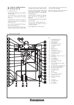
For safety reasons the P.C.B. envisions a fuse
that cannot be restored in series with the electric
power supply of the gas valve.
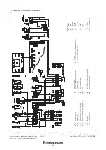
3.2 230 V CIRCUIT WIRING DIAGRAM.
Ke
y:
A2
-
P.C.B
.
A4
-
D
isp
la
y b
oa
rd
E
1
-
Ig
ni
tio
n e
lec
trode
E
2
-
D
et
ec
tio
n e
lec
trode
G2
-
Ig
ni
ter
M1
-
Bo
iler ci
rcu
la
to
r p
um
p
M20
-
Fa
n
M30
-
Th
re
e-w
ay v
al
ve (o
pt
io
na
l)
S1
-
M
ai
n s
w
itc
h
X90
-
Bo
iler c
on
fig
ur
at
io
n j
um
per
Y1
-
G
as v
al
ve
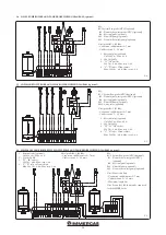
Configure the corresponding parameters when
connecting in “simple cascade”, or when con-
necting in “system side flow probe”, or “D.H.W.
pump”.
1
-
Ext
er
na
l r
es
et (o
pt
io
na
l)
2
-
Al
ar
m.
Fr
ee c
on
ta
ct M
ax.
230 V
ac - 0,8 A M
ax. c
osφ ≥ 0,6
3
-
Sys
tem s
id
e p
um
p P
ot
en
tia
l.
Fr
ee c
on
ta
ct M
ax.
230 V
ac - 0,8 A M
ax. c
osφ ≥ 0,6
4
-
Ext
er
na
l r
ela
y (o
pt
io
na
l)
5
-
Co
il 230 V
ac - M
ax. 0.1 A
6
-
Ext
er
na
l p
um
p (D
riv
en b
y M1 p
um
p)
7
-
D.H.W
. p
um
p
Col
ou
r k
ey
:
BK
-
Bl
ac
k
BL
-
Bl
ue
BR
-
Br
ow
n
G
-
Gr
een
GY
-
Gr
ey
O
R
-
O
ra
nge
P
-
Pu
rp
le
PK
-
Pin
k
R
-
Re
d
Y
-
Ye
llo
w
Y/G
-
Ye
llo
w / G
re
en
W
-
W
hi
te
W/BK
-
W
hi
te / B
la
ck
Содержание VICTRIX PRO 35 2ErP
Страница 1: ...IE Instruction and warning book VICTRIX PRO 35 55 2 ErP 1 041662ENG...
Страница 2: ......
Страница 38: ...38 3 15 1 6 8 9 9 12 12 10 11 13 13 13 13 A A Rif A 7 7 Ref A...
Страница 49: ...49...
Страница 50: ...50...
Страница 51: ...51...


